Automatic cable punching method capable of accurately positioning

An accurate positioning and cable technology, which is applied in the direction of boring/drilling, drilling/drilling equipment, metal processing equipment, etc., to achieve the effect of improving accuracy and efficiency and reducing technical and operating experience requirements

Active Publication Date: 2018-08-17
SOUTH CHINA UNIV OF TECH
View PDF8 Cites 0 Cited by
  • Summary
  • Abstract
  • Description
  • Claims
  • Application Information

AI Technical Summary

Problems solved by technology

[0003] The invention provides an automatic cable punching method capable of accurate positioning, the purpose of which is to overcome the shortcomings of the existing manual punching technology, and by using the automatic punching method of the present invention, the requirements of automatic, fast and accurate positioning of the cable punching can be realized , which laid the foundation for the arrangement of thermocouples in each layer of the cable and the measurement of temperature

Method used


Image

  • Automatic cable punching method capable of accurately positioning
  • Automatic cable punching method capable of accurately positioning
  • Automatic cable punching method capable of accurately positioning

Examples


Embodiment 1

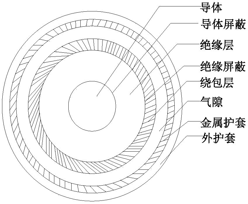
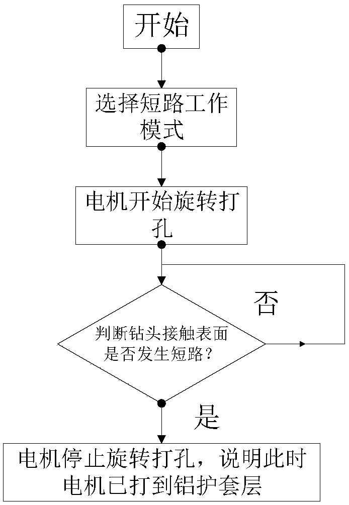
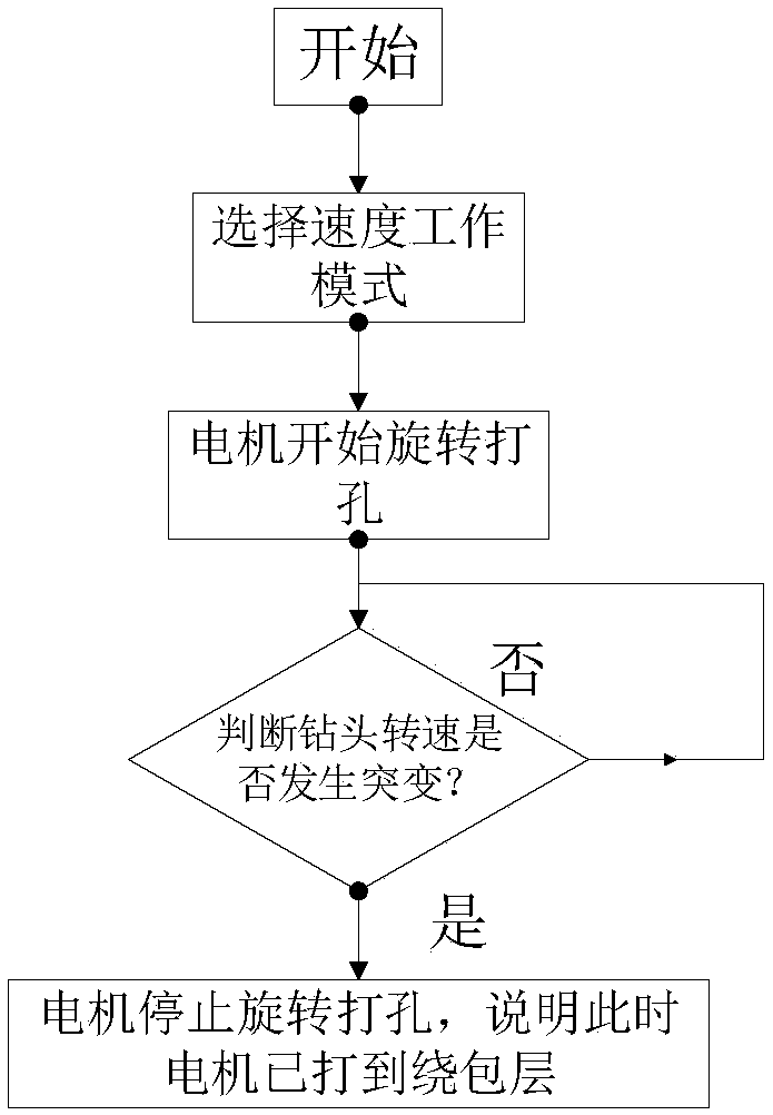
[0026] This embodiment discloses an automatic cable punching method capable of accurate positioning. The punching is performed based on the cable punching motor. The working modes of the punching motor include: 1) short-circuit working mode, which is determined by judging whether a short circuit occurs on the contact surface of the drill bit. Whether the drill bit should stop working; 2) Speed ​​work mode, that is, determine whether the drill bit should stop working by judging whether the drill bit rotation speed changes suddenly; 3) Distance work mode, that is, set a target distance, when the drill bit advances to reach the target distance , the drill stops working; 4) Jog mode, that is, when the jog button is pressed, the drill stops working after rotating for 0.1s.

[0027] Attached below Figure 6 Specifically introduce the method for automatic punching of cables, including the following steps:

[0028] S1. Based on the radial section of the cable, firstly adjust the work...

Embodiment 2

[0040] The cable punching method for accurate positioning described in this embodiment is 64 / 110kV 1×630mm for single-core cables 2 The single-core cable is automatically punched, and the details are as follows:

[0041] S1. Based on the radial section of the 110kV single-core cable, first switch the working mode of the motor to the short-circuit working mode, and drill holes in the cable until the drill bit stops working, indicating that the drill bit has hit the aluminum sheath layer of the cable at this time.

[0042] S2. Adjust the working mode of the motor to the jogging working mode, and jog the cable for 0.1s to punch holes. This is a treatment for better arranging thermocouples on the surface of the metal layer.

[0043]S3. Adjust the working mode of the motor to the speed working mode, and drill the cable until the drill bit stops working, indicating that the drill bit has hit the wrapping layer at this time.

[0044] S4. Adjust the working mode of the motor to the d...


PUM


Abstract

The invention discloses an automatic cable punching method capable of accurately positioning. The automatic cable punching method comprises the following steps of (S1) adjusting an operating mode of amotor to a short circuit operating mode on the basis of the radial profile of a cable first, and punching the cable until a drill stops operating; (S2) adjusting to an inching operating mode, and performing inching punching on the cable; (S3) adjusting to a speed operating mode, and punching the cable until the drill stops operating; (S4) adjusting to a distance operating mode, and punching the cable by selecting a set value on the basis of the type and parameters of the cable until the drill stops operating, wherein the condition shows that the cable is punched to an insulating layer at themoment; (S5) adjusting to the short circuit operating mode again, punching the cable until the drill stops operating, then adjusting to the inching operating mode, and performing inching punching treatment on the cable until all layers of the cable are punched. According to the automatic cable punching method, on the basis of an automatic control theory, the automatic cable punching with accuratepositioning is realized, and the automatic cable punching method has a high application value in engineering practice.

Description

technical field [0001] The invention relates to the technical field of power cable state monitoring, in particular to an automatic cable drilling method capable of accurate positioning. Background technique [0002] With the development of transmission and distribution networks, power cables are widely used in urban transmission and distribution networks. The continuous increase in the demand for electric energy in the current society has brought increasingly severe challenges to the safe operation of the power system, and the current carrying capacity of power cables has continued to increase, even exceeding its design limit. High-voltage transmission cables mainly use cross-linked polyethylene as the insulating material, and their current carrying capacity is determined by the long-term allowable maximum operating temperature of the insulating material. In actual operation, the working temperature of the insulating material is the temperature of the outer surface of the c...

Claims


Application Information

Patent Timeline
Patent Type & Authority Applications(China)
IPC IPC(8): B23B41/00B23B35/00
CPCB23B35/00B23B41/00
Inventor 刘刚王鹏宇许志锋陈泳锋
Owner SOUTH CHINA UNIV OF TECH
Why Eureka
Try Eureka