Vertical hot sleeving process method for flange end-free long and thin main shaft

A shrink-fit process without flanges, used in metal processing, manufacturing tools, metal processing equipment, etc., can solve the problems of difficulty in assembling components for shrink-fit, over-limited lifting height, etc., shortening the installation cycle, reducing lifting height, heating low cost effect

Inactive Publication Date: 2018-08-17
HARBIN ELECTRIC MASCH CO LTD
View PDF5 Cites 3 Cited by
  • Summary
  • Abstract
  • Description
  • Claims
  • Application Information

AI Technical Summary

Problems solved by technology

[0002] For high-speed suspended hydro-generator sets, one shaft structure is often used, and the two ends of the main shaft of the one shaft structure are slender, the middle is thicker, and the shaft diameter is small. For hubs or thin-walled parts, use the vertical heat fit of the main shaft and fix it through the flange end of the main shaft. The fixing method must be firm to ensure that the main shaft is perpendicular to the ground, so as to ensure that the heat fit parts and the mating section of the main shaft are coaxial, and meet the requirements of the drawings after the heat fit parts. The required tightness, and the vertical spindle often has the problem of lifting height exceeding the limit, which brings difficulties to shrink-fit components
However, for the spindle without flange end, the general vertical shrink fitting process method cannot meet the actual needs. Therefore, how to optimize the vertical shrink fitting process method of a spindle, fix the shaft scientifically and rationally, improve the safety of the shrink fitting and Reliability has become a new topic that technicians urgently need to solve

Method used


Image

  • Vertical hot sleeving process method for flange end-free long and thin main shaft
  • Vertical hot sleeving process method for flange end-free long and thin main shaft
  • Vertical hot sleeving process method for flange end-free long and thin main shaft

Examples


Embodiment Construction

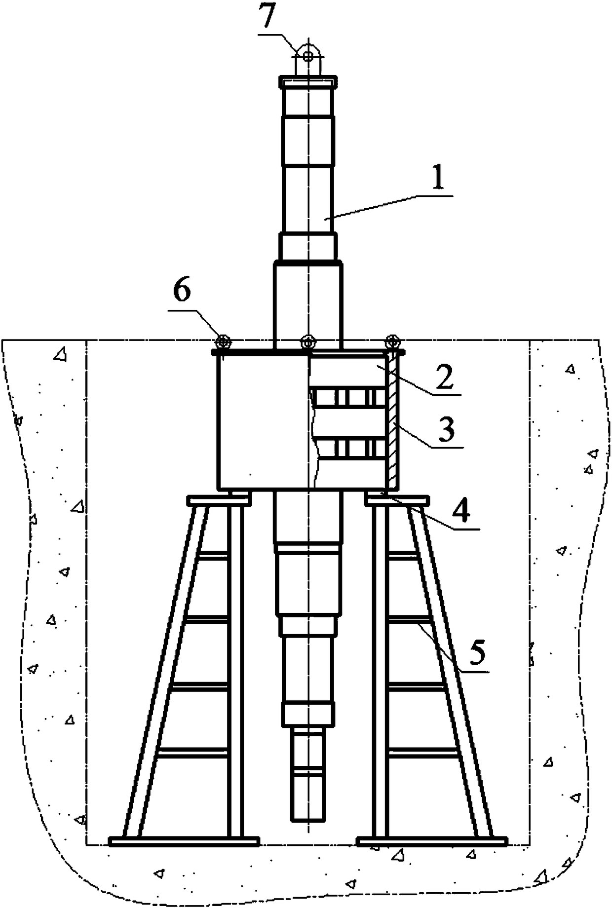
[0020] a. Prepare support frame 5, hoisting tool 7, lifting rope, adjusting pad 4, etc. according to the size of the main shaft drawing and the weight of the main shaft, see figure 1 .

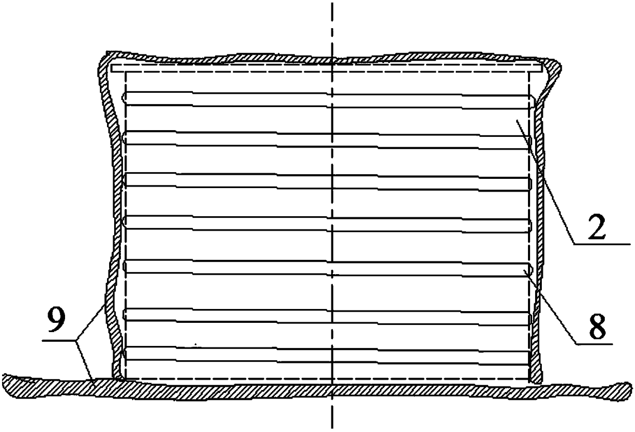
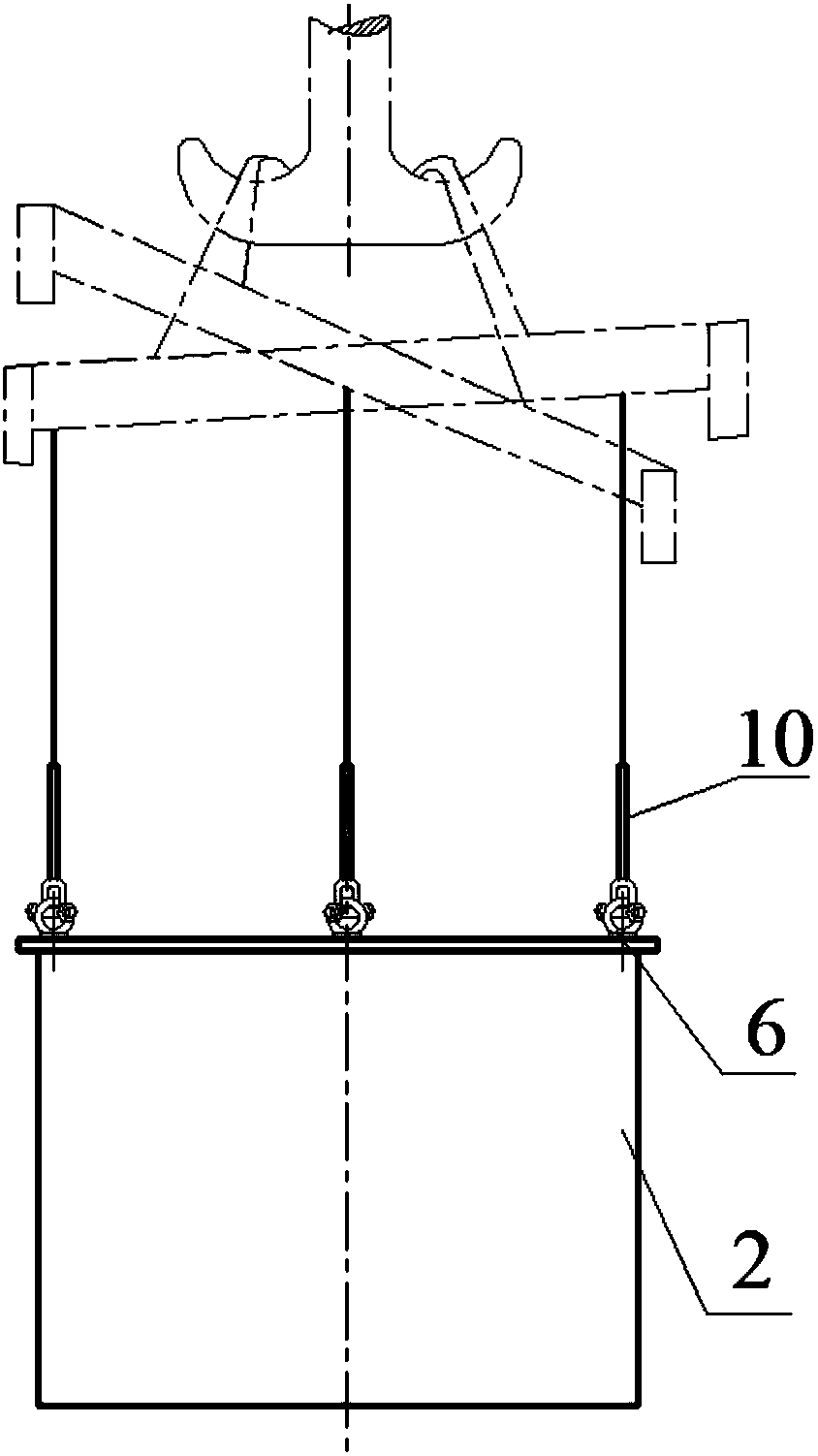
[0021] b. Preparation before heat-fitting: spread the high-temperature-resistant and heat-insulating ceramic fiber cloth 9 on the platform, install four lifting lugs on the upper end of the thin-walled part 2, lift the thin-walled part 2 onto the platform, and let the ceramic fiber Place cloth 9 under the thin-walled part 2, and then remove the four lifting lugs, see figure 2 .

[0022] c. Wrap two layers of ceramic fiber cloth 9 on the outer surface of the thin-walled part 2, then wrap the insulated electromagnetic induction wire 8 on the ceramic fiber cloth 9 outside the thin-walled part 2, and wrap it tightly. Thin-walled parts 2 and the upper surface are wrapped with a layer of ceramic fiber cloth 9 for heat preservation, connected to a power supply for heating, see figure 2 .

[002...


PUM


Abstract

The invention discloses a vertical hot sleeving process method for a flange end-free long and thin main shaft. By means of the process method, the requirement for the fastening amount obtained after the flange end-free long and thin main shaft and a thin-walled part are subjected to hot sleeving can be met, and the hot sleeving efficiency and the assembling quality are improved. The fixing mannerof the main shaft without a flange end after erecting is fundamentally innovated, pit installation stations of a workshop are utilized, the situation that too much space is occupied due to the fact that a climbing scaffold is erected is avoided, the problem that the height exceeds limitation when a component is hoisted during hot sleeving is also avoided, the hot sleeving preparation and assemblyperiod is shortened, the hot sleeving safety is improved, the installation stations and tools can also be utilized for a long time, and the installation cost is greatly reduced.

Description

technical field [0001] The invention discloses a process method of a vertical heat sleeve of a slender main shaft without a flange end. Background technique [0002] For high-speed suspended hydro-generator sets, one shaft structure is often used, and the two ends of the main shaft of the one shaft structure are slender, the middle is thicker, and the shaft diameter is small. For hubs or thin-walled parts, use the vertical heat fit of the main shaft and fix it through the flange end of the main shaft. The fixing method must be firm to ensure that the main shaft is perpendicular to the ground, so as to ensure that the heat fit parts and the mating section of the main shaft are coaxial, and meet the requirements of the drawings after the heat fit parts. The required tightness, and the vertical spindle often has the problem of lifting height exceeding the limit, which brings difficulties to shrink-fit components. However, for the spindle without flange end, the general vertica...

Claims


Application Information

Patent Timeline
Patent Type & Authority Applications(China)
IPC IPC(8): B23P11/02B66C13/04
CPCB23P11/025B66C13/04
Inventor 宋佳音韩济远尚培轩王新洪韩旭东张行明盖兆滨马永良
Owner HARBIN ELECTRIC MASCH CO LTD
Why Eureka
Try Eureka