Machine and method for forming free curved surfaces of silicate glass
A silicate glass and forming machine technology, applied in glass forming, glass reshaping, glass production, etc., can solve the problems of lower product yield and quality, fast mold cooling speed, glass bursting, etc., to improve production The effect of high efficiency, fast heating rate and low consumption
- Summary
- Abstract
- Description
- Claims
- Application Information
AI Technical Summary
Problems solved by technology
Method used
Image
Examples
Embodiment 1
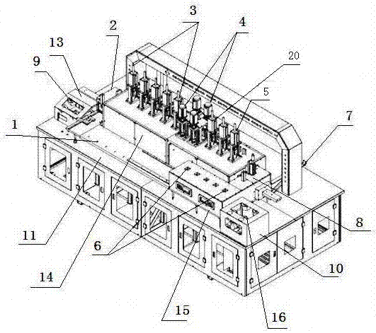
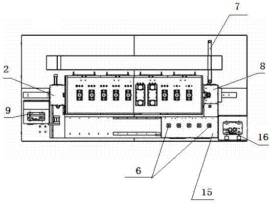
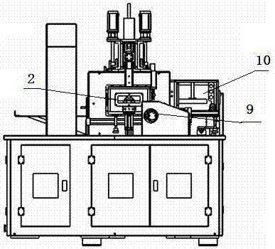
[0028] A silicate glass free-form surface molding machine, which consists of: a box body 11, the upper plane of the box body is fixed to the workbench 1, and a furnace chamber 14 and a cooling chamber 15 are respectively installed above the workbench. The cooling chamber described above is installed at the front end of the furnace chamber, and the two sides of the furnace chamber respectively have a feed chamber 2 and a discharge chamber 8, and a pusher mechanism B is installed on the right side of the cooling chamber. No.: 10, the left side of the workbench is connected with the pusher mechanism A, part number: 13 through bolts, and the furnace cavity is respectively equipped with a preheating device 3, a forming device 4, a shaping device 20, and a slow cooling device 5. There is a cooling device 6 inside the cooling cavity.
Embodiment 2
[0030] According to the silicate glass free-form surface molding machine described in Embodiment 1, it is characterized in that: two heating plates 21 distributed up and down are installed in the preheating device, the molding device and the shaping device , a pneumatic device is installed in the preheating device, a pressurizing device is installed in the forming device, a group of water cooling plates distributed up and down are installed in the cooling device, and a group of measuring Temperature device 22, a group of heating tubes 23.
Embodiment 3
[0032] According to the silicate glass free-form surface molding machine described in Example 1, the pushing device A includes a power device A, and the power device A is connected to the furnace chamber shift fork 9, and the furnace chamber shift fork is located at Inside the furnace cavity.
PUM
 Abstract
Description
Claims
Application Information
 - R&D
- Intellectual Property
- Life Sciences
- Materials
- Tech Scout
- Unparalleled Data Quality
- Higher Quality Content
- 60% Fewer Hallucinations
Browse by: Latest US Patents, China's latest patents, Technical Efficacy Thesaurus, Application Domain, Technology Topic, Popular Technical Reports.
© 2025 PatSnap. All rights reserved.Legal|Privacy policy|Modern Slavery Act Transparency Statement|Sitemap|About US| Contact US: help@patsnap.com


