A rudder-controlled jet dual-rotor aircraft

An aircraft and dual-rotor technology, applied in the field of rotorcraft, can solve the problems of poor maneuverability control sensitivity and accuracy, small rotor carrying capacity, etc., and achieve the effects of sensitive control, large carrying capacity, and small control torque

Active Publication Date: 2021-01-08
ANHUI UNIVERSITY OF TECHNOLOGY
View PDF9 Cites 0 Cited by
  • Summary
  • Abstract
  • Description
  • Claims
  • Application Information

AI Technical Summary

Problems solved by technology

[0003] In order to overcome the disadvantages of the existing rotorcraft, such as small rotor bearing capacity and poor maneuverability control sensitivity and accuracy, the present invention provides a rudder-controlled jet dual-rotor aircraft

Method used


Image

  • A rudder-controlled jet dual-rotor aircraft
  • A rudder-controlled jet dual-rotor aircraft
  • A rudder-controlled jet dual-rotor aircraft

Examples


Embodiment Construction

[0018] The present invention will be further described below in conjunction with the accompanying drawings and specific embodiments.

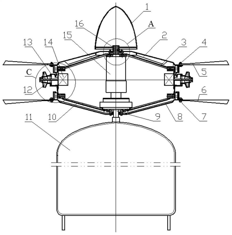
[0019] figure 1 It is a front view assembly diagram of a rudder-controlled jet dual-rotor aircraft. The fairing 1, the hollow shaft 16, the upper guide ring 2a, the upper impeller 2 and the upper blade 5 are fixedly connected to form an upper rotor symmetrical to the axis of the hollow shaft 16, and the upper output shaft of the power unit 15 is fixedly connected to the hollow shaft to drive the upper rotor turn.

[0020] The lower disc 8, the lower guide ring 8a and the lower blade 6 are fixedly connected to form a lower rotor symmetrical to the axis of the lower disc, and the lower output shaft of the power unit 15 is fixedly connected to the lower disc to drive the lower rotor to rotate. The upper part of the power unit 15 is fixedly connected with the upper casing 3, and its lower part is fixedly connected with the lower casing 10 to form...


PUM


Abstract

The invention discloses a rudder-controlled jet double-rotor aircraft and belongs to the technical field of an aircraft. The rudder-controlled jet double-rotor aircraft consists of a power cabin, an upper rotor, a lower rotor, a power device, a rudder controlling device, bearing wheel trains, a load cabin and the like. The upper rotor is located above the power cabin and the lower rotor is locatedunder the power cabin. Nozzles of a rudder controlling system are located between the upper rotor and the lower rotor and are distributed on the outer circumference of the power cabin. Bearing wheeltrains are distributed on the upper and lower circumference of the power cabin and maintain contact with the upper and lower rotors to bear axial load of the upper and lower rotors. The power device drives the upper rotor and the lower rotor to rotate with equal speed in the opposite direction and lift power and location and pose controlling thrust required by an aircraft are produced, size and direction of the controlling thrust are changed by a rudder machine. The rudder-controlled jet double-rotor aircraft has high engine driven performance and facilitates control of flight and landing in complex space; meanwhile, the rudder controlling device is simple in mechanism, compact in structure and has the independent power cabin and load cabin, and is high in safety.

Description

technical field [0001] The invention belongs to the technical field of rotorcraft, in particular to a rudder-controlled jet dual-rotor aircraft. Background technique [0002] A rotorcraft is an aircraft that controls the lift and maneuverability of the aircraft by changing the lift of the rotor and the pitch of the blades. It has stronger maneuverability than a fixed-wing aircraft. It does not require a runway for take-off and landing, and can take off and land vertically, fly at low speed or Hover, adapted to fly in complex spaces. The main rotor and power unit of a general rotorcraft are located in the middle and front of the load compartment, and the tail rotor is located at the tail of the load compartment. The cantilever length of the main rotor is large, the carrying capacity is small, and the flight resistance is large. To control the air attitude and maneuverability of the aircraft, the structure is complex and the cost is high. At the same time, the power compartm...

Claims


Application Information

Patent Timeline
Patent Type & Authority Patents(China)
IPC IPC(8): B64C27/08B64C27/46B64C1/32
CPCB64C1/32B64C27/08B64C27/46
Inventor 张玉华张维王旭泉王孝义
Owner ANHUI UNIVERSITY OF TECHNOLOGY
Why Eureka
Try Eureka