Oil return pipe joint and installation tool thereof

A technology for installing tools and oil return pipes, used in manufacturing tools, lubricant conduit devices, hand-held tools, etc., can solve the problems of temperature rise of housing and transmission parts, sealing ring cutting, low production efficiency, etc., to improve installation Reliability and tightness, improved installation speed, uniform force effect

Active Publication Date: 2018-08-17
BEIJING FOTON CUMMINS ENGINE
View PDF6 Cites 0 Cited by
  • Summary
  • Abstract
  • Description
  • Claims
  • Application Information

AI Technical Summary

Problems solved by technology

However, due to the high temperature of the exhaust gas and the high-speed rotation of the impeller, it will cause the temperature rise and serious wear of the housing and transmission parts, so a steady stream of oil is needed to cool, clean and ensure transmission efficiency
[0003] Considering the assembly size and the interference of parts, etc., the oil return pipe joint of the supercharger currently used has a special shape and small size, so it is difficult for the operator to find the force application point during the installation process, and the uneven force will cause the sealing ring to cut , causing a more serious problem of engine oil leakage
At the same time, due to the particularity of the structural shape, high-frequency installation will cause severe soreness in the fingers of workers, affecting CT time (Cycle Time, the average time required to complete a product), and lower production efficiency

Method used


Image

  • Oil return pipe joint and installation tool thereof
  • Oil return pipe joint and installation tool thereof
  • Oil return pipe joint and installation tool thereof

Examples


Embodiment Construction

[0039] Specific embodiments of the present invention will be described in detail below in conjunction with the accompanying drawings. It should be understood that the specific embodiments described here are only used to illustrate and explain the present invention, and are not intended to limit the present invention.

[0040] Based on the problem in the prior art that it is difficult to find the point of application of force when installing the oil return pipe joint, and the improper installation position may easily lead to oil leakage, the present invention provides an oil return pipe joint and an installation tool that can solve the above technical problems. Hereinafter, the oil return pipe joint and the installation tool will be described in detail through specific embodiments and in conjunction with corresponding drawings.

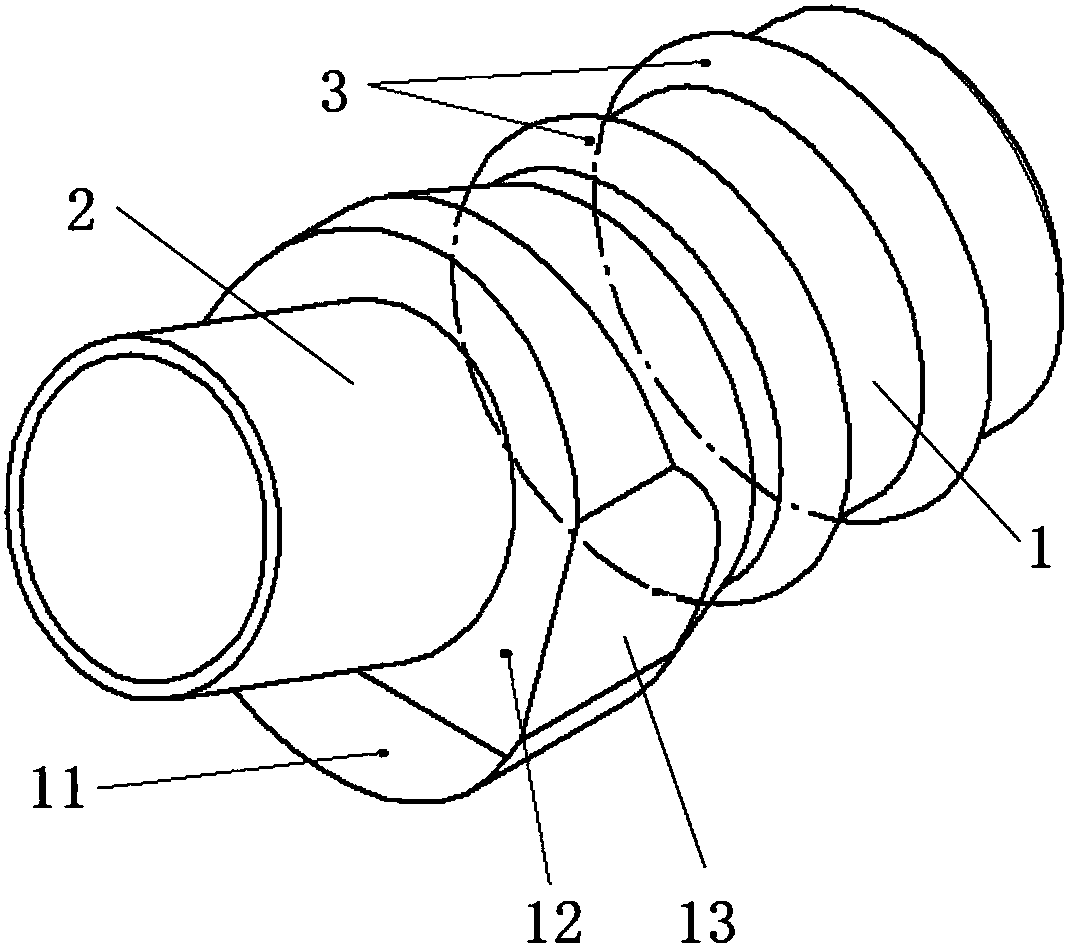
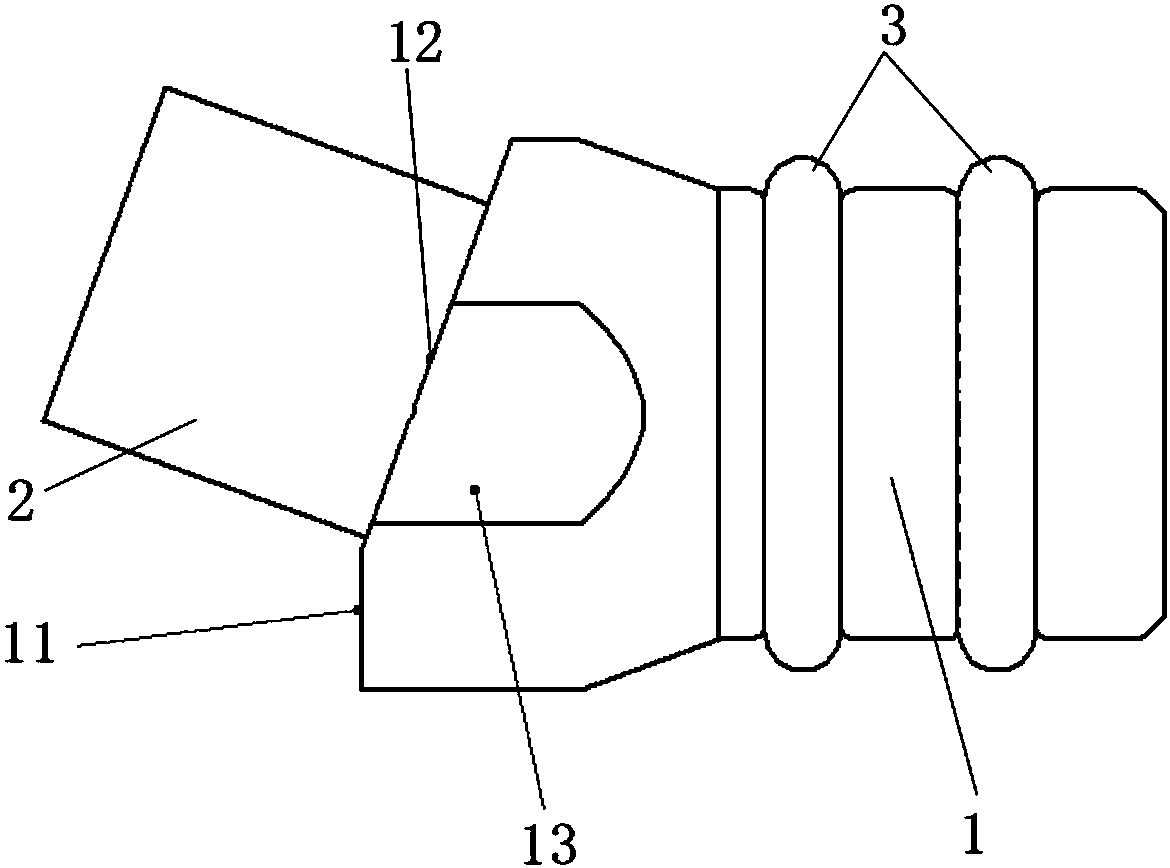
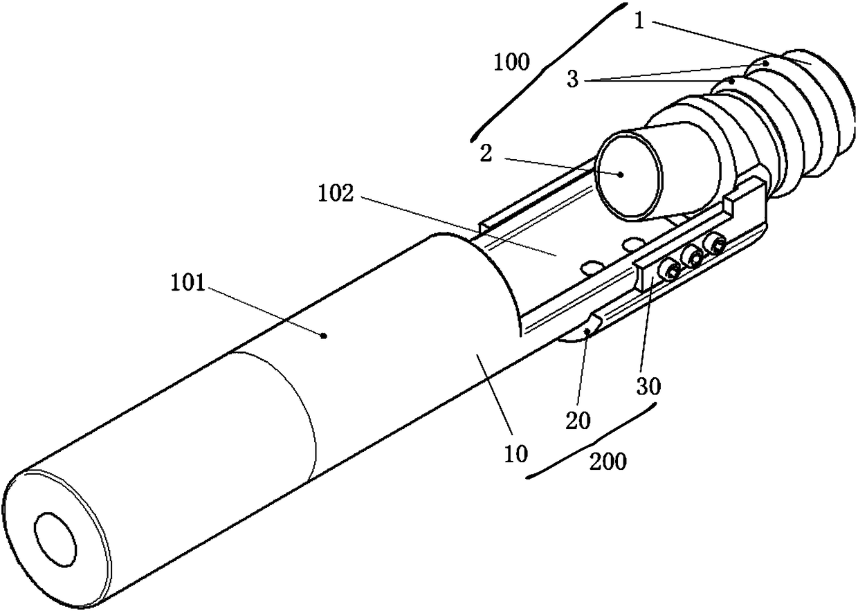
[0041] According to one aspect of the present invention, appropriate reference figure 1 and figure 2 The oil return pipe joint provided by the pres...


PUM


Abstract

The invention relates to the technical field of a turbocharged engine, and discloses an oil return pipe joint and an installation tool thereof. The oil return pipe joint comprises: a first pipe body (1), wherein a first end of the first pipe body is connected to an oil return hole of an engine cylinder, an end surface of a second end of the first pipe body includes a first plane (11) and a secondplane (12) for receiving the assembly force, the first plane is perpendicular to a central line of the first pipe body, and the second plane and the central line of the first pipe body form an obtuseangle from the second end to the first end; and a second pipe body (2), wherein the second pipe body is connected to an oil return pipe of a supercharger, and the second tube body and the first tube body are connected in the second plane. According to the oil return pipe joint of the present invention, the first pipe body has the first plane and the second plane, the first plane and the second plane can simultaneously bear the thrust of the installation tool of the present invention, and the force is uniform. The installation reliability and sealing performance of the oil return pipe joint isimproved, and the installation speed is accelerated.

Description

technical field [0001] The invention relates to the technical field of turbocharged engines, in particular to an oil return pipe joint and an installation tool for installing the oil return pipe joint. Background technique [0002] A turbocharged engine refers to an engine equipped with a turbocharger. When the engine speed increases, the turbocharger can use the kinetic energy of the exhaust gas to increase the turbine speed synchronously, and the coaxial compressor impeller rotates to greatly increase the pressure and density of the intake air, so that the engine can burn more fully. , to increase the output power. However, due to the high temperature of the exhaust gas and the high-speed rotation of the impeller will cause the temperature rise and serious wear of the housing and transmission parts, a continuous flow of oil is needed to cool, clean and ensure transmission efficiency. [0003] Considering the assembly size and the interference of parts, etc., the oil retu...

Claims


Application Information

Patent Timeline
IPC IPC(8): F01M11/02F02B39/14B25B27/00
CPCB25B27/0028F01M11/02F02B39/14
Inventor 郑建业黄海萍
Owner BEIJING FOTON CUMMINS ENGINE
Why Eureka
Try Eureka