
Heating system based on solar cogeneration assembly

A technology for cogeneration and heating systems, which can be applied in heating systems, household heating, heating methods, etc. Effect

Inactive Publication Date: 2018-08-17
NINGXIA BLACK GOLD TECH CO LTD
View PDF5 Cites 0 Cited by
  • Summary
  • Abstract
  • Description
  • Claims
  • Application Information

AI Technical Summary

Problems solved by technology

[0005] In order to solve the problem of low utilization efficiency of solar energy in the prior art, the application provides a heating system based on solar cogeneration components

Method used


Image

  • Heating system based on solar cogeneration assembly
  • Heating system based on solar cogeneration assembly

Examples


Embodiment 1

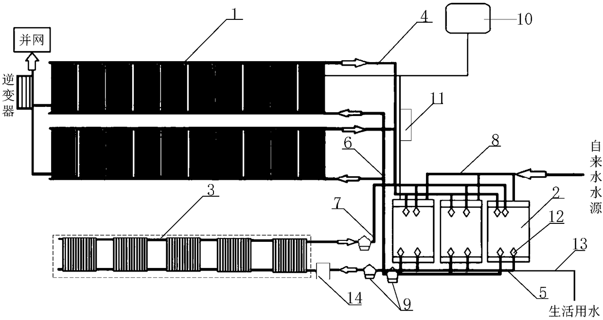
[0029] see figure 1 Shown is a schematic structural diagram of a heating system based on solar cogeneration components provided in this application. The heating system includes a solar cogeneration assembly 1, a heat storage tank 2, and a heating device 3. The solar cogeneration assembly 1 includes a liquid flow channel of a heat exchange tube, and is arranged below the liquid flow channel of the heat exchange tube. Insulation layer, the insulation layer is made of microcrystalline foam board,

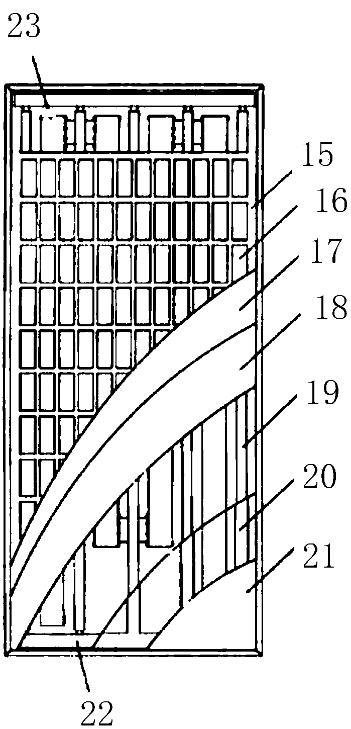
[0030] The outlet 23 of the liquid channel of the heat exchange tube communicates with the inlet of the heat storage tank 2 through the first pipeline 4;

[0031] The outlet of the heat storage tank 2 is connected to the water inlet of the heating device 3 through the second pipeline 5, and the outlet of the heat storage tank 2 is also connected to the liquid flow channel of the heat exchange tube through the third pipeline 6. The entrances 22 are connected;

[0032] The water outle...

Embodiment 2

[0036] see figure 1 Shown is a schematic structural diagram of a heating system based on solar cogeneration components provided in this application. The heating system includes a solar cogeneration assembly 1, a heat storage tank 2, and a heating device 3. The solar cogeneration assembly 1 includes a liquid flow channel of a heat exchange tube, and is arranged below the liquid flow channel of the heat exchange tube. Insulation layer, said insulation layer selects microcrystalline foam board 20 for use,

[0037] The outlet 23 of the liquid channel of the heat exchange tube communicates with the inlet of the heat storage tank 2 through the first pipeline 4;

[0038] The outlet of the heat storage tank 2 is connected to the water inlet of the heating device 3 through the second pipeline 5, and the outlet of the heat storage tank 2 is also connected to the liquid flow channel of the heat exchange tube through the third pipeline 6. The entrances 22 are connected;

[0039]The wat...


PUM


Abstract

The invention relates to the technical field of solar cogeneration, and particularly relates to a heating system based on a solar cogeneration assembly. The heating system comprises the solar cogeneration assembly, a heat storage tank and a heating device, wherein the solar cogeneration assembly comprises a heat exchange tube liquid flow channel and an insulating layer; the insulating layer is made of a microcrystalline foaming board which has the advantages of smooth surface, high light absorption, good insulation performance, low heat dissipation, good corrosion resistance and difficulty inbreaking; the heat storage tank is used for storing heat energy converted from sunlight, and heat exchange with common tap water is performed, so that hot water for heating and domestic hot water aresupplied to residents; and the heating device is used for increasing the indoor temperature for residents by utilizing hot water, so that the indoor temperature for residents can reach 18 to 25 DEG C.According to the heating system, the solar cogeneration assembly is additionally arranged, so that a solar photothermal technique and a photovoltaic power generation technique can be utilized at thesame time, the solar comprehensive utilization efficiency is improved, and the heating system has wide application prospects.

Description

technical field [0001] The present application relates to the technical field of solar cogeneration, in particular to a heating system based on solar cogeneration components. Background technique [0002] With the continuous development of science and technology, renewable energy has become an important energy resource in my country, which plays an important role in meeting energy demand, improving energy structure, reducing environmental pollution, and promoting economic development. As a renewable energy source, solar energy has the advantages of wide distribution of resources, huge total amount, clean, inexhaustible and inexhaustible. Therefore, the development and utilization of solar energy is of great significance for saving conventional energy, protecting the natural environment, and mitigating climate change. At present, the research on solar energy utilization mainly focuses on solar heating, solar photovoltaic power generation, solar thermal power generation, sola...

Claims


Application Information

Patent Timeline
Patent Type & Authority Applications(China)
IPC IPC(8): F24D15/02F24D19/10
CPCY02B10/20Y02B10/70F24D15/02F24D19/1096
Inventor 黑建忠黑小龙黑小军
Owner NINGXIA BLACK GOLD TECH CO LTD
Learn More