
Optical collimation beam-expanding system

A beam expander system and optical collimation technology, which is applied in the field of optical collimation beam expander system to achieve the effects of simple mechanical control, simple structure and large dynamic adjustment range

Inactive Publication Date: 2018-08-17
INST OF OPTICS & ELECTRONICS - CHINESE ACAD OF SCI
View PDF5 Cites 0 Cited by
  • Summary
  • Abstract
  • Description
  • Claims
  • Application Information

AI Technical Summary

Problems solved by technology

The above technology is only applicable to the case where the output laser beam’s aperture in the x direction is equal to the aperture in the y direction, and the divergence angle in the x direction is equal to the divergence angle in the y direction. There is a moving mirror, and the above technology cannot guarantee the final target beam when the laser transmission distance changes. The clear aperture and divergence angle meet the requirements of use

Method used


Image

  • Optical collimation beam-expanding system
  • Optical collimation beam-expanding system
  • Optical collimation beam-expanding system

Examples


Embodiment Construction

[0022] In order to better illustrate the purpose and advantages of the present invention, the present invention will be further described below with reference to the drawings and specific embodiments.

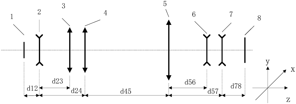
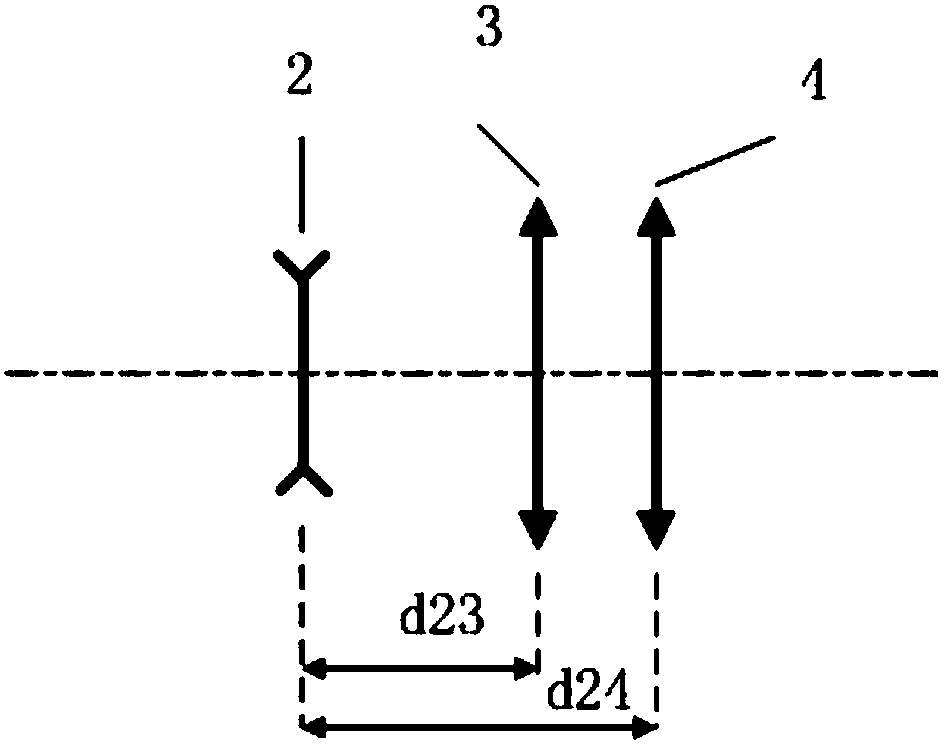
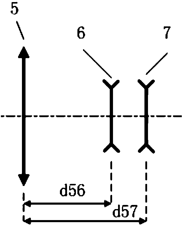
[0023] figure 1 It is a schematic diagram of the principle of the optical collimation and expansion system. The optical collimation and expansion system consists of a first spherical mirror 2, a first cylindrical mirror 3 and a second cylindrical mirror 4, a second spherical mirror 5, a third cylindrical mirror 6 and a fourth cylindrical mirror. The cylindrical mirror 7 is constituted. The first spherical mirror 2 and the first cylindrical mirror 3 and the second cylindrical mirror 4 form a set of collimating beam expanders, which expand the laser beam emitted by the laser 1; then perform laser transmission, the second spherical mirror 5 and the third The cylindrical mirror 6 and the fourth cylindrical mirror 7 form a group of collimating beam expanders, which collimate the transm...


PUM


Abstract

The invention provides an optical collimation beam-expanding system so that a problem that the beam caliber and divergence angle of the laser beam can not meet user needs at different transmission distances according to the high NA lithography technology can be solved. The optical collimation beam-expanding system is composed of two spherical mirrors and four cylindrical mirrors; the focal powersof the two cylindrical mirrors are in a y direction and the focal powers of the other two cylindrical mirrors are in an x direction; the single spherical mirror and cylindrical mirrors in different focal power directions form one group of collimation beam-expanding devices. The system has two groups of collimation beam-expanding devices; the first group of collimation beam-expanding devices expandlaser beams and thus laser is transmitted in a range of 5 to 20 meters; and then the second group of collimation beam-expanding devices collimate the laser beams, so that the beam in the x directionand the beam in the y direction can meet the caliber and divergence angle requirements. The optical collimation beam-expanding system has advantages of having a simple structure and being easy to process and adjust; no follower is provided at different transmission distances; and mechanical control is realized easily.

Description

Technical field [0001] The invention relates to an optical collimation beam expansion system, which belongs to the technical field of lithography illumination. Background technique [0002] Since the birth of optical projection exposure technology in 1978, it has experienced several technological development stages such as g-line, i-line, 248nm, and 193nm. In just a few decades since its emergence, the integrated circuits related to the optical projection exposure technology have gone through several development stages such as small-scale, ultra-large-scale, and extremely large-scale, strongly traction by the process of social informatization. Large-scale integrated circuits have become the cornerstone of the development of high-tech fields. From satellites, rockets and other aerospace fields, to radars, laser-guided missiles, and defense fields, as well as people’s daily lives, very large-scale integrated circuits are inseparable. It is the main information processing device an...

Claims


Application Information

Patent Timeline
Patent Type & Authority Applications(China)
IPC IPC(8): G02B27/09G02B27/30
CPCG02B27/0955G02B27/0966G02B27/30
Inventor 范真节邢廷文林妩媚李声廖志杰
Owner INST OF OPTICS & ELECTRONICS - CHINESE ACAD OF SCI
Learn More