Cable post-processing, dewatering and drying device
A drying device and cable technology, applied in the direction of insulated cables, cable/conductor manufacturing, cables, etc., can solve problems such as low efficiency, blocked ventilation holes, and poor water removal effect
- Summary
- Abstract
- Description
- Claims
- Application Information
AI Technical Summary
Problems solved by technology
Method used
Image
Examples
Embodiment 1
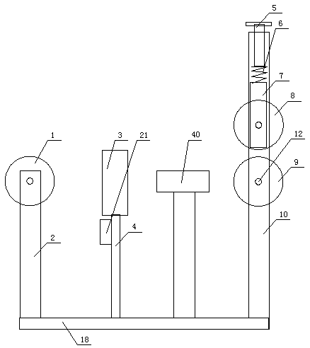
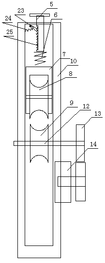
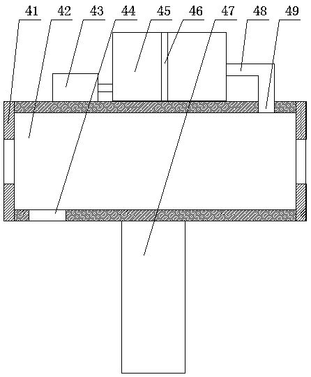
[0027] A cable post-processing water removal and drying device, comprising a front support frame 3 and a rear support frame 2 arranged on a base 18, the rear support frame is provided with a driven wire pulley 1, the front support frame and the rear support frame A dewatering mechanism is provided between the frames, and a cable drive mechanism is provided on the front support frame, and the cable drive mechanism includes a driving wire pulley 9 arranged on the front support frame, and a vertical sliding mechanism is provided in the front support frame. Slide block 7, described slide block is provided with the compression wire wheel 8 that rotates and connects, and described front support frame is provided with through hole, is provided with the depression rod 5 that is used for compressing slide block in described through hole, described Teeth 25 are provided on the pressure bar, pawls 23 are provided in the support frame, and a tensioning spring 24 is provided between the paw...
Embodiment 2
[0037] A cable post-processing water removal and drying device, comprising a front support frame 3 and a rear support frame 2 arranged on a base 18, the rear support frame is provided with a driven wire pulley 1, the front support frame and the rear support frame A dewatering mechanism is provided between the frames, and a cable drive mechanism is provided on the front support frame, and the cable drive mechanism includes a driving wire pulley 9 arranged on the front support frame, and a vertical sliding mechanism is provided in the front support frame. Slide block 7, described slide block is provided with the compression wire wheel 8 that rotates and connects, and described front support frame is provided with through hole, is provided with the depression bar that is used for compressing slide block 7 in described through hole, described Teeth are provided on the pressure rod, pawls are provided in the support frame, and a tension spring is provided between the pawl and the fr...
Embodiment 3
[0045] A cable post-processing water removal and drying device, comprising a front support frame 3 and a rear support frame 2 arranged on a base 18, the rear support frame is provided with a driven wire pulley 1, the front support frame and the rear support frame A dewatering mechanism is provided between the frames, and a cable drive mechanism is provided on the front support frame, and the cable drive mechanism includes a driving wire pulley 9 arranged on the front support frame, and a vertical sliding mechanism is provided in the front support frame. Slide block 7, described slide block is provided with the compression wire wheel 8 that rotates and connects, and described front support frame is provided with through hole, is provided with the depression bar that is used for compressing slide block in described through hole, and described pressure Teeth are provided on the rod, pawls are provided in the support frame, and a spring is arranged between the pawl and the front su...
PUM
| Property | Measurement | Unit |
|---|---|---|
| Thickness | aaaaa | aaaaa |
| Tensile strength | aaaaa | aaaaa |
| Strain rate | aaaaa | aaaaa |
Abstract
Description
Claims
Application Information
 - R&D
- Intellectual Property
- Life Sciences
- Materials
- Tech Scout
- Unparalleled Data Quality
- Higher Quality Content
- 60% Fewer Hallucinations
Browse by: Latest US Patents, China's latest patents, Technical Efficacy Thesaurus, Application Domain, Technology Topic, Popular Technical Reports.
© 2025 PatSnap. All rights reserved.Legal|Privacy policy|Modern Slavery Act Transparency Statement|Sitemap|About US| Contact US: help@patsnap.com


