A weldment anti-deformation device

An anti-deformation and weldment technology, applied in auxiliary devices, welding equipment, auxiliary welding equipment, etc., can solve the problems of low cooling efficiency and weldment stress deformation, and achieve the goal of reducing welding cost, improving welding efficiency and welding quality. Effect

Active Publication Date: 2020-01-31
WEICHAI POWER CO LTD
View PDF7 Cites 0 Cited by
  • Summary
  • Abstract
  • Description
  • Claims
  • Application Information

AI Technical Summary

Problems solved by technology

[0004] The object of the present invention is to provide a weldment anti-deformation device to solve the problems of low cooling efficiency and stress deformation of the weldment when the existing weldment is welded

Method used


Image

  • A weldment anti-deformation device
  • A weldment anti-deformation device
  • A weldment anti-deformation device

Examples


Embodiment 1

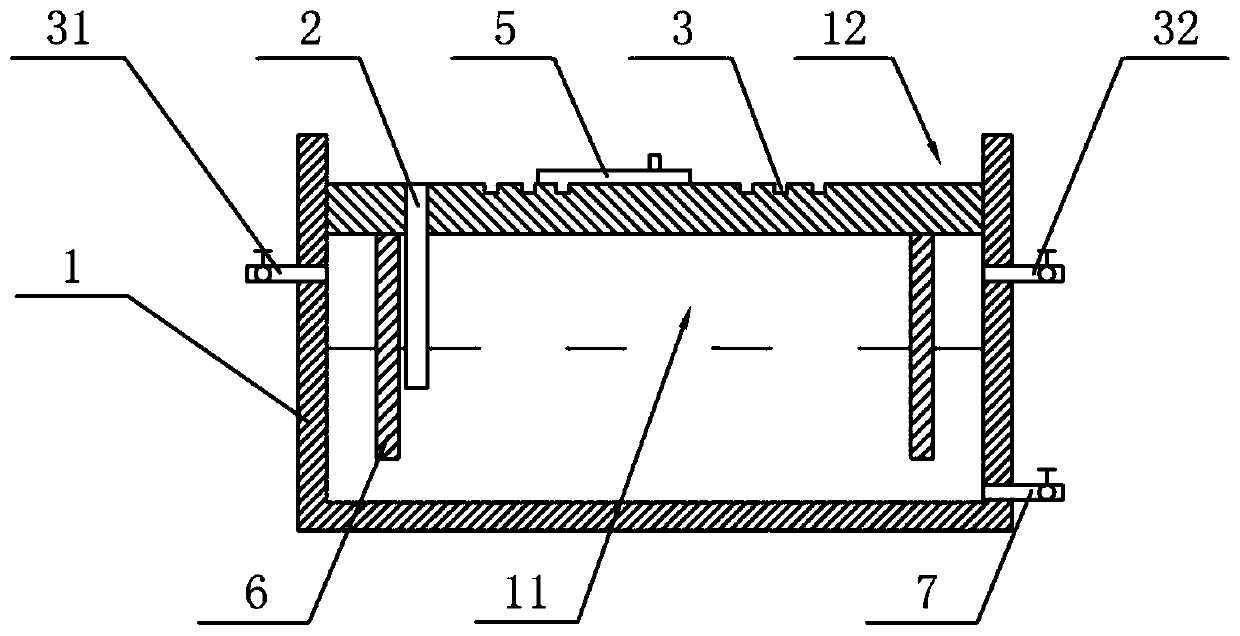
[0032] This embodiment provides a weldment anti-deformation device, such as figure 2 as well as image 3 As shown, the weldment anti-deformation device includes a box body 1, a diversion channel 2, a gas valve, a weldment positioning component and a liquid control valve 7, wherein:

[0033] The box body 1 is provided with a cavity 11 inside, and a groove 12 is arranged at the top, and the weldment is placed in the groove 12, and is welded with other weldments in the groove 12 . Cooling liquid is placed inside the cavity 11 , and the volume of the cooling liquid is no more than two-thirds of the volume of the cavity 11 . In this embodiment, the above-mentioned box body 1 has a cylindrical structure, and the box body 1 is made of metal materials. Of course, the structure of the box body 1 in this embodiment is not limited to a cylindrical shape, and other structures such as a rectangular shape may also be used.

[0034] In this embodiment, one end of the flow guide channel 2...

Embodiment 2

[0048] The difference between the present embodiment and the first embodiment is only that the structure of the diversion channel 2 is different. The present embodiment does not set the cooling liquid conduit and the ring plate 6. For details, please refer to Figure 5 as well as Figure 6 , the guide channel 2 of this embodiment includes a connection plate 21 fixed to the top wall and side wall of the cavity 11, a cavity 24 is formed between the connection plate 21 and the top wall and side wall of the cavity 11, and at the same time A liquid outlet 22 communicating with the chamber 24 is opened on the top wall of the cavity 11 . Specifically, a liquid inlet 23 is provided at the bottom of the connecting plate 21, and the liquid inlet 23 will communicate with the chamber 24 and the cavity 11. When high-pressure gas is input into the cavity 11, the high-pressure gas can make the air The cooling liquid in the cavity 11 flows into the groove 12 through the liquid inlet 23 and t...


PUM


Abstract

The invention belongs to the technical field of welding jigs and discloses a weldment deformation-preventing device. The weldment deformation-preventing device comprises a box body, a flow guide channel, a gas valve and a weldment positioning assembly, wherein the box body is internally provided with a cavity for containing cooling liquid, and the top of the box body is provided with a groove; oneend of the flow guide channel communicates with the groove, and the other end of the flow guide channel is arranged in the cooling liquid in the cavity; the gas valve communicates with the cavity; and the weldment positioning assembly is arranged in the groove and used for fixing a weldment to be welded. By means of the weldement deformation-preventing device, when a weldment is welded, firstly,the weldment is fixed through the weldment positioning assembly, then, high-pressure gas is fed into the cavity, the high-pressure gas extrudes the cooling liquid in the cavity into the groove to immerse the fixed end of the weldment, in the welding process, real-time, rapid and effective cooling is carried out on the welding line position of the weldment through the cooling liquid, and thereforeit is ensured that the weldement deformation and other problems caused by welding point heat concentration and unsmooth heat dissipation cannot occur to the weldment. The welding efficiency and the weldment quality are effectively improved, and the welding cost is reduced.

Description

technical field [0001] The invention relates to the technical field of welding fixtures, in particular to a welding piece anti-deformation device. Background technique [0002] During the engine bench test, there is usually a modification to the bench test pipeline. During the modification process, some welding such as figure 1 Clamp style stainless steel fittings shown in . There are two weldments in the figure: stainless steel clamp joint 101 and stainless steel straight pipe 102. During the welding process of stainless steel clamp joint 101 and stainless steel straight pipe 102, if the heat dissipation at weld 103 is not good, it is easy to cause heat concentration at the solder joint. , the problem of deformation of the sealing surface 104 of the stainless steel clamp joint 101 caused by untimely heat dissipation, and any slight deformation may cause subsequent assembly of two butt stainless steel clamp joints 101. The sealing surface 104 between 101 is not tightly sea...

Claims


Application Information

Patent Timeline
Patent Type & Authority Patents(China)
IPC IPC(8): B23K37/00B23K37/04
CPCB23K37/003B23K37/0443
Inventor 魏春修王文龙郭继强于光霁孙卫顺
Owner WEICHAI POWER CO LTD
Why Eureka
Try Eureka