
Manufacturing method of acoustic lens transducer array

A technology of transducer array and manufacturing method, which is applied in the direction of re-radiation of sound waves, instruments, and utilization of re-radiation, etc., and can solve problems such as failure to meet the requirements of high main-side lobe ratio, deformation, and strong echo signals

Active Publication Date: 2017-04-26
山东蓝鲸腾飞海洋科技有限公司
View PDF6 Cites 0 Cited by
  • Summary
  • Abstract
  • Description
  • Claims
  • Application Information

AI Technical Summary

Problems solved by technology

[0004] In the prior art, the acoustic lens transducer is a transducer line array composed of rectangular array elements. When the array element has a tilt angle, the echo signal received by the side lobe is very strong, which cannot meet the requirement of high main-side lobe ratio in the vertical direction.
[0005] In order to increase the main-side lobe ratio in the vertical direction, the existing technology uses the finished acoustic lens transducer to form a three-dimensional bending type through external force, and when filling the polymer between the array elements, it needs to be filled according to a certain polymer filling shape. , and these operations have high requirements on equipment and technology, and the external force exerts pressure on the finished acoustic lens transducer, and there are problems such as side shift and deformation

Method used


Image

  • Manufacturing method of acoustic lens transducer array
  • Manufacturing method of acoustic lens transducer array
  • Manufacturing method of acoustic lens transducer array

Examples


Embodiment Construction

[0041] The following will clearly and completely describe the technical solutions in the embodiments of the present invention with reference to the accompanying drawings in the embodiments of the present invention. Obviously, the described embodiments are only some, not all, embodiments of the present invention. Based on the embodiments of the present invention, all other embodiments obtained by persons of ordinary skill in the art without making creative efforts belong to the protection scope of the present invention.

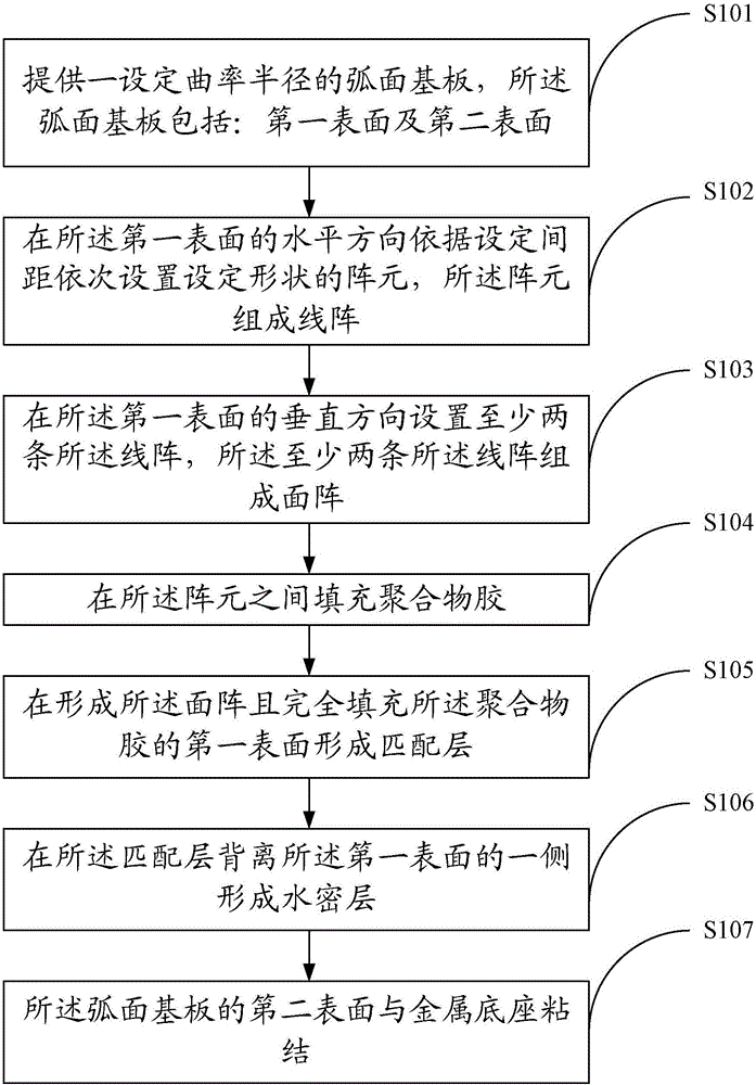
[0042] refer to figure 1 , figure 1 It is a schematic flowchart of a method for manufacturing an acoustic lens transducer array provided by an embodiment of the present invention. The production method includes:

[0043] S101: Provide a curved substrate with a set radius of curvature, the curved substrate includes: a first surface and a second surface.

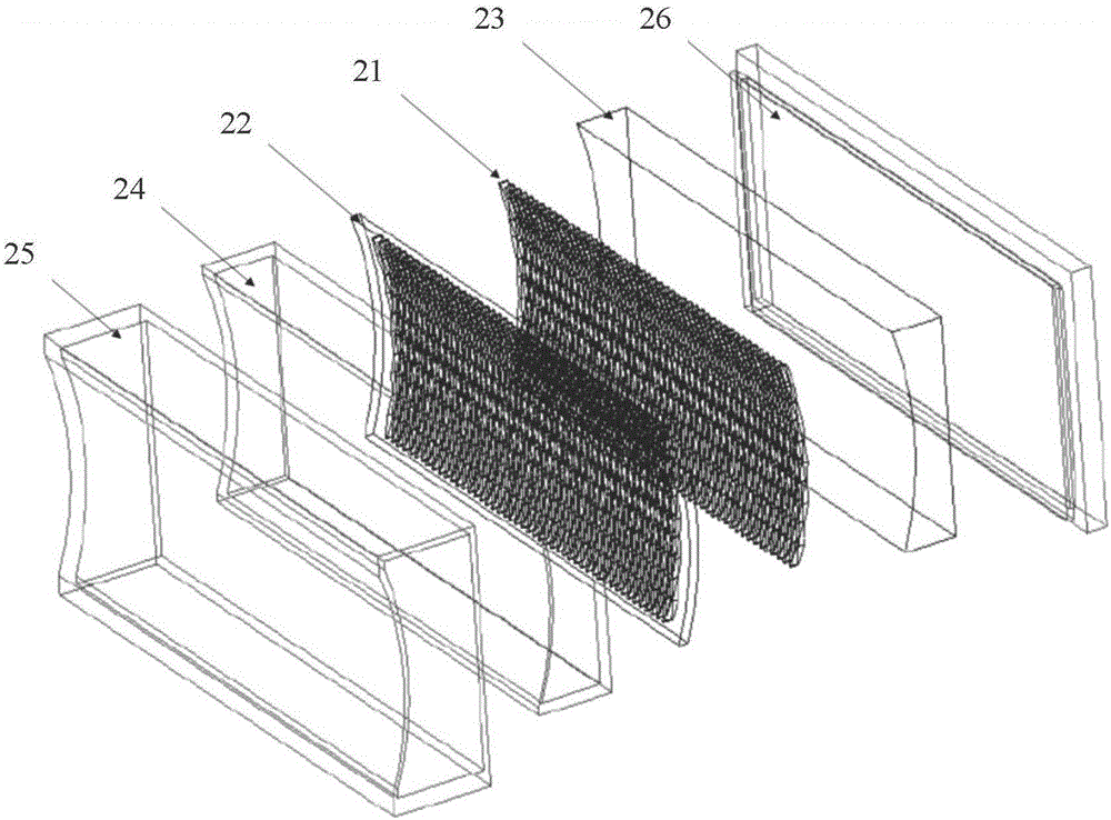
[0044] refer to figure 2 , figure 2 A schematic diagram of the composition structure of an acoustic ...


PUM


Abstract

The invention provides a manufacturing method of an acoustic lens transducer array. The manufacturing method comprises the following steps of providing a cambered surface substrate with a setting radius of curvature, wherein the cambered surface substrate includes a first surface and a second surface; successively arranging array elements with a set shape according to a set distance along a horizontal direction of the first surface, wherein the array elements form linear arrays; arranging the at least two linear arrays at a vertical direction of the first surface, wherein the at least two linear arrays form a surface array; filling a polymer glue among the array elements; forming a matching layer on the first surface which forms the surface array and is completely filled with the polymer glue; forming a watertight layer on one side of the matching layer, wherein the side is deviated from the first surface; and bonding the second surface of the cambered surface substrate with a metal pedestal. By using the manufacturing method, the high-gain acoustic lens transducer array can be acquired and three-dimensional imaging is realized.

Description

technical field [0001] The invention relates to the technical field of underwater transducers, and more specifically, relates to a method for manufacturing an acoustic lens transducer array. Background technique [0002] With the continuous development of science and technology, in the application of underwater high-definition acoustic imaging, offshore engineering implementation, port surveillance, frogman detection, mine and mine-type target recognition, obstacle avoidance and navigation of underwater vehicles, acoustic lens energy conversion Appliances play a very important role. [0003] The high-gain acoustic lens transducer uses acoustic lens technology and 1-3 composite material configuration technology to output a transducer with a high main-side lobe ratio in the horizontal and vertical directions. For a good acoustic image, not only a narrow beam of the acoustic lens transducer is required, but also very low sidelobes of the acoustic lens transducer beam. [0004...

Claims


Application Information

Patent Timeline
Patent Type & Authority Applications(China)
IPC IPC(8): G01S7/523G01S15/89
CPCG01S7/523G01S15/89
Inventor 黄勇王春玲王荣刚
Owner 山东蓝鲸腾飞海洋科技有限公司
Learn More