
Method for measuring influence range of ionic rare earth single well injection under condition of constant water heads

A measurement method, a technology of constant water head, which is applied in the field of determination of the influence range of ionic rare earth single well injection, and can solve problems such as oversaturation of mountains, dead angles and blind areas of ore leaching, and effects on the full recovery of rare earth resources.

Inactive Publication Date: 2018-08-21
JIANGXI UNIV OF SCI & TECH
View PDF4 Cites 4 Cited by
  • Summary
  • Abstract
  • Description
  • Claims
  • Application Information

AI Technical Summary

Problems solved by technology

[0006] (3) There are many studies on one-dimensional infiltration laws and infiltration models, but few three-dimensional infiltration laws and infiltration models. The research methods and methods of one-dimensional infiltration and three-dimensional infiltration are different. And the infiltration model is simplified and has certain limitations
[0007] The difficulty and significance of solving the above technical problems: The key factor in the design of in-situ leaching mining is to calculate the well pattern parameters. If the liquid injection well pattern is too dense, it will not only increase the drilling engineering volume of the liquid injection wells, but also easily cause the mountain to be oversaturated and cause landslides; if the liquid injection wells If the network layout is too sparse, many leaching dead angles and blind areas will be formed, which will affect the full recovery of rare earth resources

Method used


Image

  • Method for measuring influence range of ionic rare earth single well injection under condition of constant water heads
  • Method for measuring influence range of ionic rare earth single well injection under condition of constant water heads
  • Method for measuring influence range of ionic rare earth single well injection under condition of constant water heads

Examples


Embodiment Construction

[0041] In order to make the objectives, technical solutions and advantages of the present invention clearer, the present invention will be further described in detail below with reference to the embodiments. It should be understood that the specific embodiments described herein are only used to explain the present invention, but not to limit the present invention.

[0042] In the present invention, in the in-situ leaching of ionic rare earth, rationally setting the liquid injection well pattern is beneficial to improve the resource recovery rate, and the key link for calculating the well pattern parameters is to determine the influence range of single well liquid injection, that is, the characteristics of the wet body and its migration law .

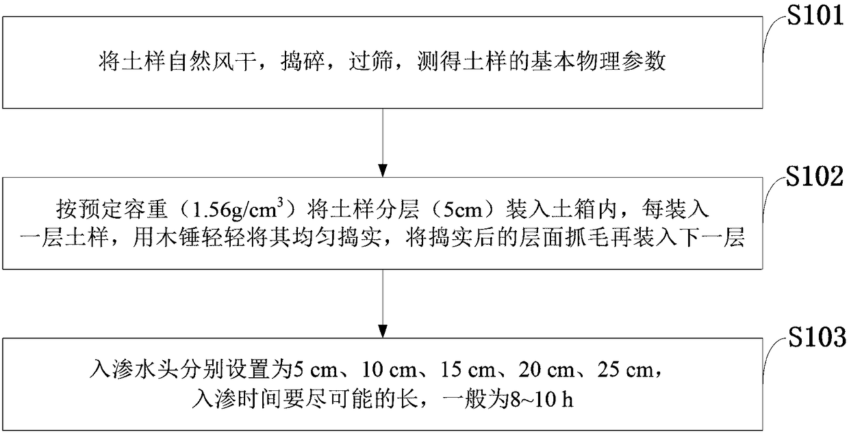
[0043] like figure 1 As shown, the method for determining the influence range of ionic rare earth single-well liquid injection under the condition of constant water head provided by the embodiment of the present invention includes the fo...


PUM


Abstract

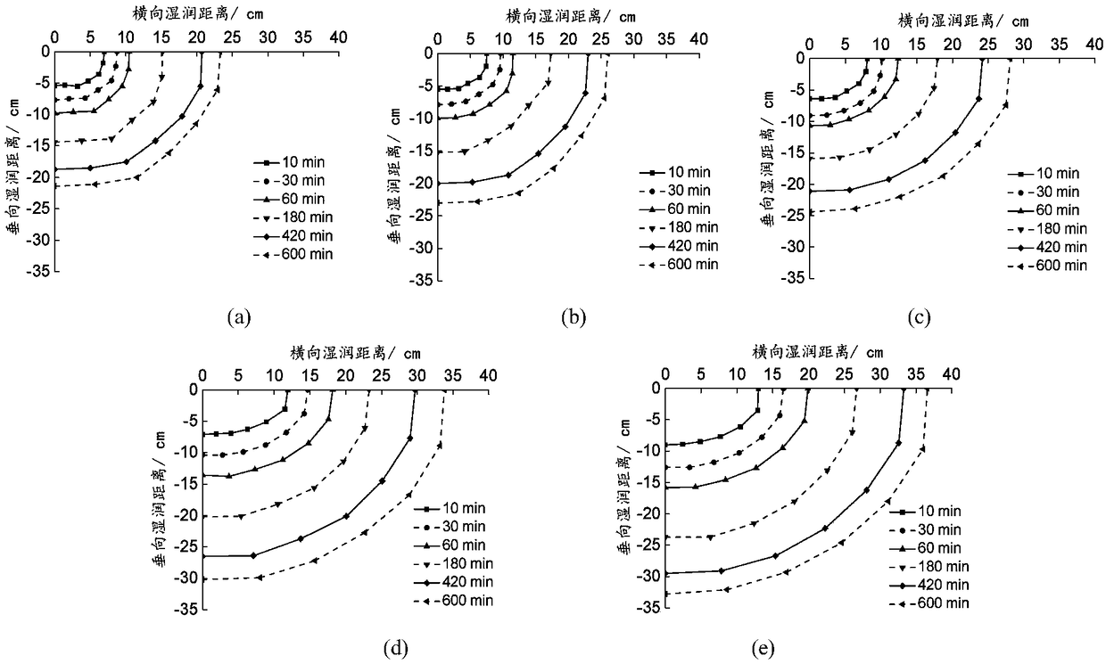
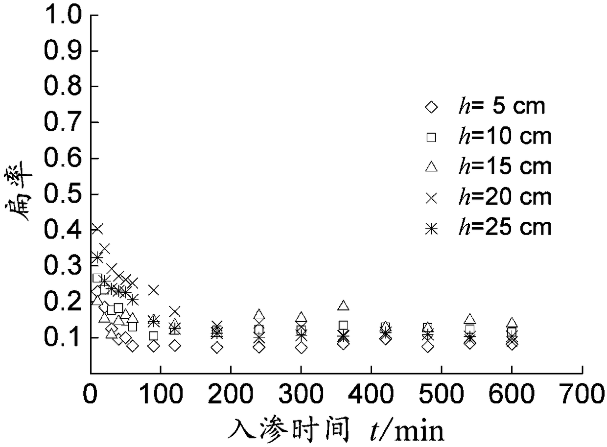
The invention belongs to the technical field of ionic rare earth leaching mining, and discloses a method for measuring the influence range of ionic rare earth single well injection under the conditions of constant water heads. It is known by rare earth infiltration tests under the conditions of different constant water heads that a wetting body is approximated as a semi-ellipsoid. The lateral wetting distance is larger than the vertical wetting distance at the initial stage of infiltration. With the infiltration, the vertical wetting front grows faster than the transverse wetting front. The shape of the wetting body develops from the semi-ellipsoid to a hemisphere; a significant linear relationship exists between the volume of the wetting body and the cumulative infiltration capacity, andthe average moisture content increment in the soil wetting body remains basically constant; a very significant function relationship exists between the horizontal and vertical maximum wetting distanceand infiltration time; a wetting body feature value calculation model is established, and model results and test results are high in goodness of fit and have application value.

Description

technical field [0001] The invention belongs to the technical field of ionic rare earth solution leaching mining, in particular to a method for measuring the influence range of ionic rare earth single well injection under the condition of constant water head. Background technique [0002] At present, the existing technologies commonly used in the industry are as follows: Ion-adsorbed rare earth (abbreviated as ionic rare earth) is an important mineral resource unique to my country and an important mineral resource that the world pays attention to. It is rich in medium and heavy rare earths, mainly distributed in seven provinces including Jiangxi, Fujian, Guangdong, Hunan, Guangxi, Yunnan, and Zhejiang. In such deposits, rare earths are adsorbed on clay minerals in the form of hydrated cations or hydroxy hydrated cations, which have the characteristics of complete distribution, high content of high value-added elements, low radioactivity ratio, and high comprehensive utilizat...

Claims


Application Information

Patent Timeline
Patent Type & Authority Applications(China)
IPC IPC(8): G06F17/50C22B3/04C22B59/00
CPCC22B3/04C22B59/00G06F30/20Y02P10/20
Inventor 郭钟群金解放赵奎王观石
Owner JIANGXI UNIV OF SCI & TECH
Learn More