Single-and-double-ridge rectangular waveguide transmission line adaptor
A rectangular waveguide and transmission line technology, applied in the field of compact transmission line adapters, can solve the problems of large size and long wavelength of the adapter, and achieve the effect of improving computing efficiency
- Summary
- Abstract
- Description
- Claims
- Application Information
AI Technical Summary
Problems solved by technology
Method used
Image

Examples
Embodiment 1
[0072] like Figures 1 to 3 , Figures 4a~4o , Figures 5a to 5d shown.
[0073] Figures 4a~4o A cross-sectional view of an existing transmission line.
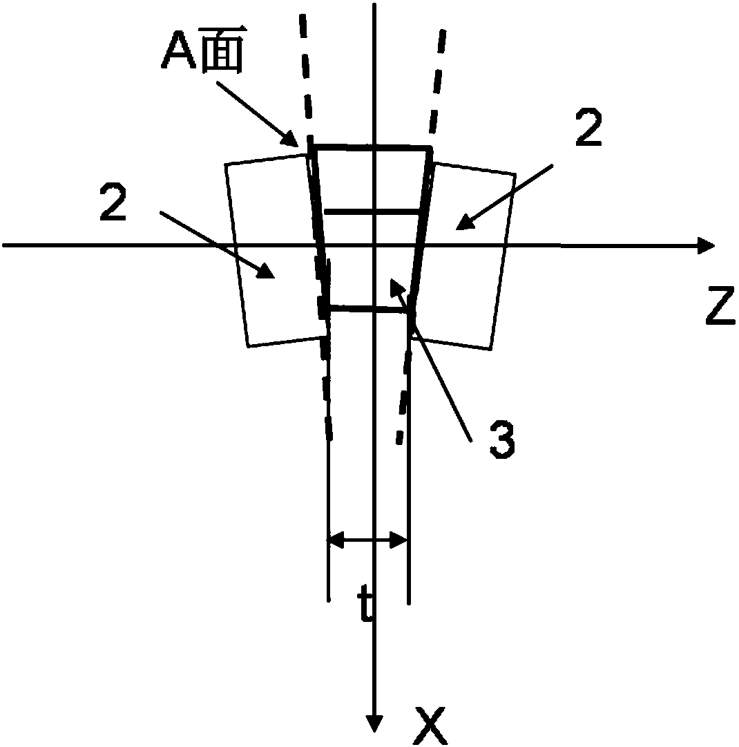
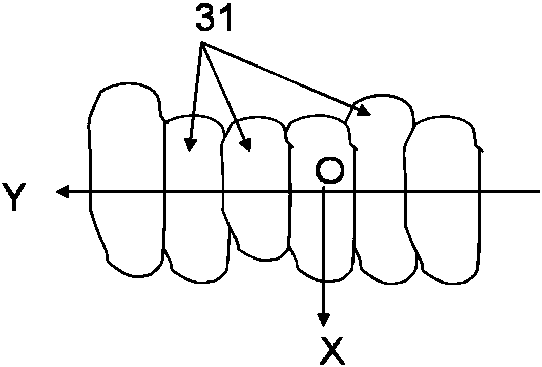
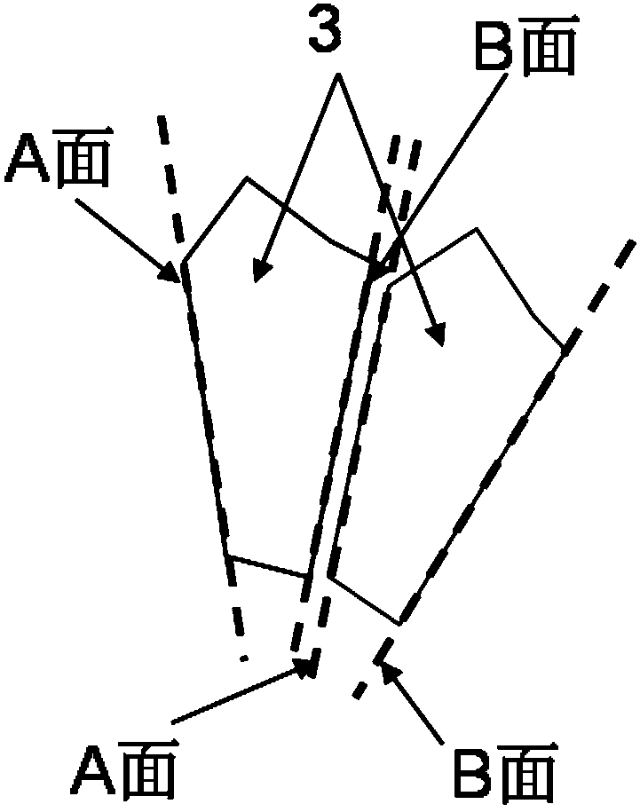
[0074] A single and double ridge rectangular waveguide transmission line adapter comprises a transmission line 2 , another transmission line 2 and an electromagnetic wave channel 3 . Both ends of the electromagnetic wave channel 3 are part of a plane A and a plane B, respectively. One end of each transmission line 2 communicates with one end of the electromagnetic wave channel 3 .
[0075] The transmission line adapter is very compact: the maximum length t of the microwave channel is less than 0.2 times the wavelength in free space corresponding to the central operating frequency of the microwave matching structure.
[0076] The transmission lines 2 are all single-ridge rectangular waveguides; the metal ridge 22 of the one transmission line 2 is connected to the bottom of the single-ridge rectangular waveguide transmis...
Embodiment 2
[0082] like Figure 6-8 shown.
[0083] The difference between this implementation example and implementation example 1 is only:
[0084] The one transmission line 2 is a cross waveguide, and the other transmission line is a quadrilateral square waveguide.
[0085] The one electromagnetic wave channel 3 communicates with one end surface of the other electromagnetic wave channel 3 through one end surface thereof.
[0086] The two electromagnetic wave channels 3 are mirror symmetrical up and down. The cross-sectional area of the electromagnetic wave channel 3 can be designed to sequentially decrease, increase, decrease and decrease from the center to the edge. The transmission line connector makes the reflection coefficient of vertically polarized electromagnetic waves lower than -20 dB in the frequency band of 19.6-23.3 GHz in the length of 1.48 mm. At the same time, the reflection coefficient of the horizontally polarized electromagnetic wave is made lower than -20dB. A...
Embodiment 3
[0088] like Figure 9-11 shown.
[0089] The main difference between this implementation example and implementation example 2 is only:
[0090] The one transmission line 2 is a single-ridged rectangular waveguide, and the other transmission line 2 is a double-ridged rectangular waveguide. The cross-sectional area of the electromagnetic channel 3 increases, increases, increases, increases, decreases, decreases, and decreases sequentially from inside to outside, so that the transmission line connector is in the range of 15 to 45 GHz within the length of 0.42 mm. Make the reflection coefficient of vertically polarized electromagnetic waves lower than -30dB. According to our careful inquiry, similar conventional techniques have not been published.
PUM
 Abstract
Description
Claims
Application Information