Relaxation oscillator and electronic device

A relaxation oscillator and capacitor technology, applied in the field of semiconductor integrated circuits, can solve the problems of large influence, reduced probability, and incomplete elimination, and achieve the effect of improving stability and eliminating self-excitation

Inactive Publication Date: 2018-08-21
SEMICON MFG INT (SHANGHAI) CORP +1
View PDF10 Cites 0 Cited by
  • Summary
  • Abstract
  • Description
  • Claims
  • Application Information

AI Technical Summary

Problems solved by technology

But there are at least two disadvantages in doing so: 1) During normal operation, the delay introduced by the comparator's slow response is to be calculated in the total

Method used


Image

  • Relaxation oscillator and electronic device
  • Relaxation oscillator and electronic device
  • Relaxation oscillator and electronic device

Examples


Embodiment 1

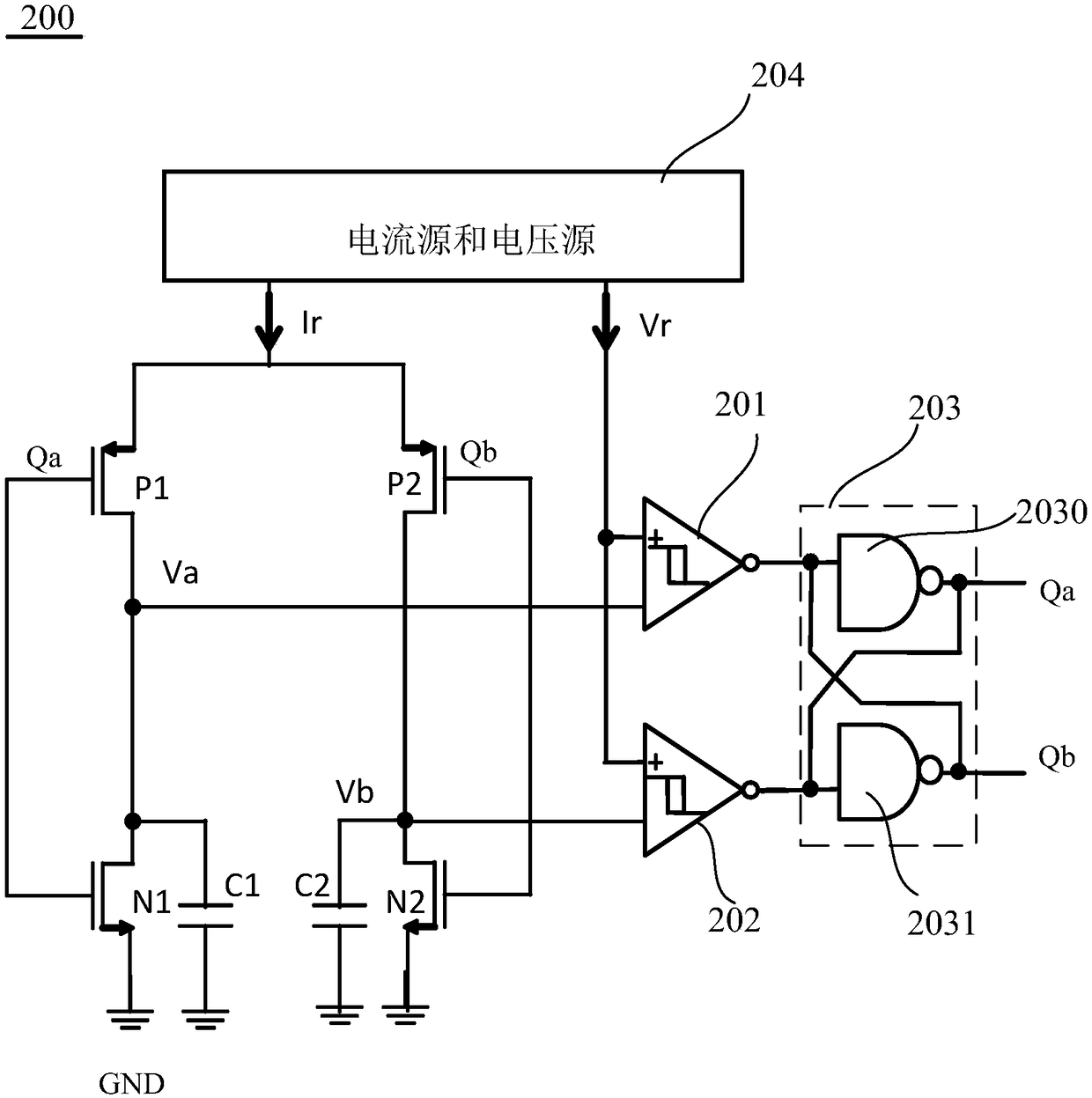
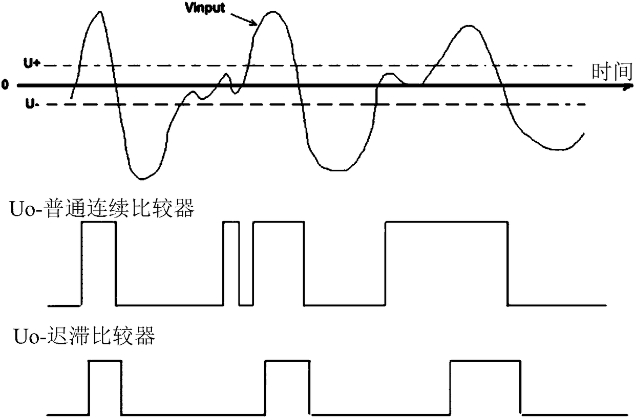
[0064] figure 2 shows a schematic circuit structure diagram of a relaxation oscillator according to the present invention; image 3 shows an exemplary comparison diagram of the input and output of a continuous comparator and a hysteretic comparator; Figure 4 Exemplary input-output curves for a hysteretic comparator are shown; Figure 5 A schematic circuit structure diagram of a hysteresis comparator according to an embodiment of the present invention is shown.

[0065] Please refer to figure 2 , the relaxation oscillator 200 of this embodiment includes: a first capacitor C1, a second capacitor C2, a first switching element N1, a second switching element P1, a third switching element N2, a fourth switching element P2, a first comparator 201 , a second comparator 202 , an RS flip-flop 203 , a current source and a voltage source 204 .

[0066] The first end of the first capacitor C1 is connected to the current source and the voltage source 204 through the first switch elem...

Embodiment 2

[0088] Still another embodiment of the present invention provides an electronic device, including the above-mentioned relaxation oscillator and an electronic component connected to the relaxation oscillator.

[0089] Wherein, the electronic component may be any electronic component such as a discrete device or an integrated circuit.

[0090] The electronic device of this embodiment can be any electronic product or equipment such as mobile phone, tablet computer, notebook computer, netbook, game console, TV set, VCD, DVD, navigator, camera, video recorder, voice recorder, MP3, MP4, PSP, etc. , can also be any intermediate product including the semiconductor device.

[0091] in, Figure 6 An example of a mobile phone is shown. The exterior of the mobile phone 600 is provided with a display portion 602 included in a casing 601, operation buttons 603, an external connection port 604, a speaker 605, a microphone 606, and the like.

[0092] The electronic device in the embodiment...


PUM


Abstract

The invention provides a relaxation oscillator and an electronic device. The relaxation oscillator comprises: a charge and discharge unit; a switch unit, configured to control the charge and dischargeunit to charge and discharge periodically; a comparator unit, configured to compare the voltage on the charge and discharge unit with a reference voltage; and a trigger unit, configured to generate an oscillating signal based on an output signal of the comparator unit and output the oscillating signal to the switch unit to control the charge and discharge unit to charge and discharge periodically; wherein the comparator unit uses a hysteresis comparator, the hysteresis voltage of the hysteresis comparator is Vh, the swing voltage of voltage signals on the charge and discharge unit is Vs, thecycle when the relaxation oscillator works is T, and the reaction time t of the trigger unit satisfies: Vh > 2Vs x t/T. The relaxation oscillator can eliminate self-excitation of a potential fast feedback loop, so that the stability of the relaxation oscillator is improved. The electronic device has similar advantages.

Description

technical field [0001] The invention relates to the technical field of semiconductor integrated circuits, in particular to a relaxation oscillator and an electronic device. Background technique [0002] In many integrated circuit applications, the clock generation circuit is an essential module. According to the requirements of different application scenarios, there are many types of clock generation circuits. figure 1 Shows a common clock generation circuit: the relaxation oscillator. Such as figure 1 As shown, the relaxation oscillator 100 includes capacitors C1, C2, four MOS transistors M1-M4, comparators 101 and 102, and an oscillating circuit composed of an RS flip-flop 103, and a current source and a voltage source 104 provide a reference current for the oscillating circuit Ir and reference voltage Vr, the latch 103 includes two inverters 1030 and 1031 . figure 1 The relaxation oscillator 100 shown uses a current source to periodically charge and discharge capacitor...

Claims


Application Information

Patent Timeline
IPC IPC(8): H03K3/0231H03K3/012H04M1/02
CPCH03K3/012H03K3/0231H04M1/02
Inventor 荀本鹏刘飞徐丽唐华朱晓明
Owner SEMICON MFG INT (SHANGHAI) CORP
Why Eureka
Try Eureka