Environmental-protection molding sand cooling recovery device

A recovery device and sand cooling technology, which is applied in the direction of casting molding equipment, cleaning/processing machinery of casting mold materials, metal processing equipment, etc., can solve the problem of poor cooling effect, affecting the next use, and unable to meet the needs of molding sand cooling, etc. problems, to achieve the effect of reducing the temperature of molding sand, reducing energy waste and improving casting precision

Inactive Publication Date: 2018-08-24
李同贵
View PDF11 Cites 6 Cited by
  • Summary
  • Abstract
  • Description
  • Claims
  • Application Information

AI Technical Summary

Problems solved by technology

[0002] During the entire recycling process, the molding sand is basically in a closed state or in a poorly ventilated state. The temperature of the castings close to the molding sand reaches 300-500°C after high temperature, and the sand temperature is above 100°C. It is difficult for the molding sand to drop to the operating temperature in a short time. Natural cooling The cooling effect cannot be achieved due to various factors and time. The high temperature of the molding sand will deteriorate the heat dissipation conditions of the casting during the next casting, seriously affect the metallographic structure and mechanical properties of the casting, and increase the possibility of pores in the casting.
In the traditional technology, the principle of humidification and cooling is generally used, the cooling effect is poor and it will affect the next use, and it can no longer meet the needs of molding sand cooling

Method used


Image

  • Environmental-protection molding sand cooling recovery device
  • Environmental-protection molding sand cooling recovery device
  • Environmental-protection molding sand cooling recovery device

Examples


Embodiment Construction

[0027] Below in conjunction with accompanying drawing and embodiment, further elaborate the present invention. In the following detailed description, certain exemplary embodiments of the invention are described by way of illustration only. Needless to say, those skilled in the art would realize that the described embodiments can be modified in various different ways, all without departing from the spirit and scope of the present invention. Accordingly, the drawings and description are illustrative in nature and not intended to limit the scope of the claims.

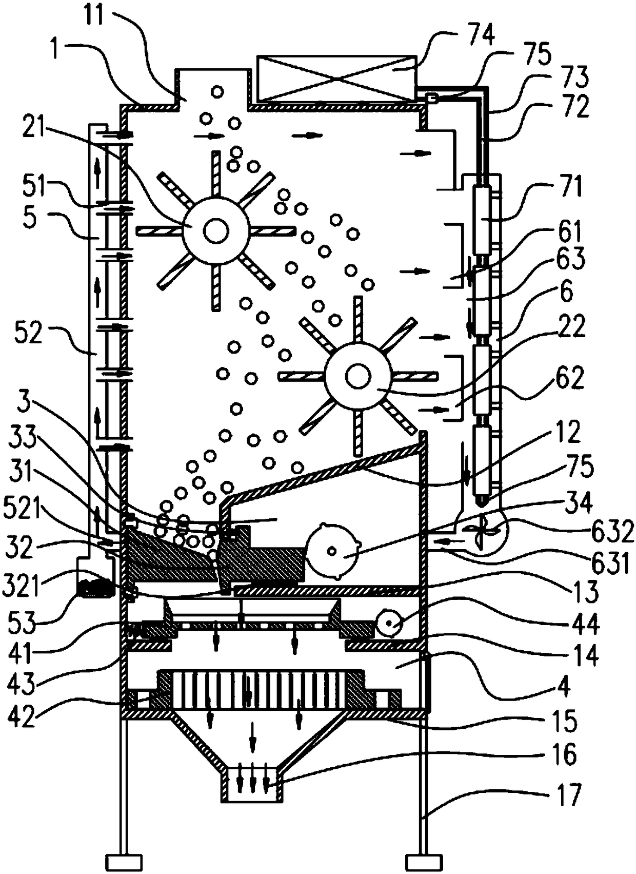
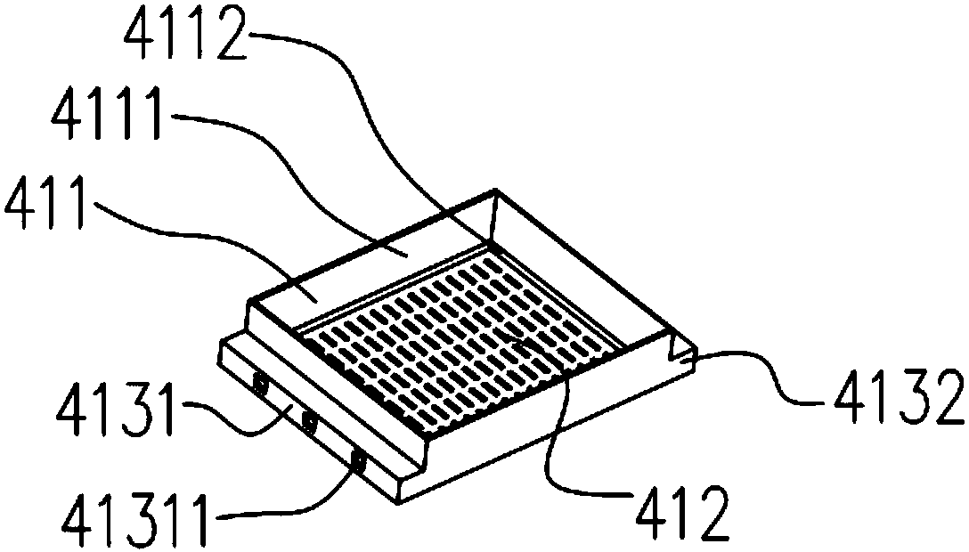
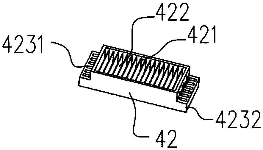
[0028] like Figure 1 to Figure 6 As shown, the environmentally friendly molding sand cooling recovery device according to this embodiment includes a tower body 1 and a first partition 12, a second partition 13 and a blanking collection plate 15 arranged in sequence from top to bottom in the tower body 1. , the upper left side of the tower body 1 is provided with a material inlet 11, the right side of the first partitio...


PUM


Abstract

The invention discloses an environmental-protection molding sand cooling recovery device. The device comprises a tower body, and a first separation plate, a second separation plate and a blanking collecting plate arranged in the tower body in sequence from top to bottom; a crushing bin is fixedly connected with a fixed inclined surface end, a slide inclined surface end and a first driving cam in sequence from left to right; a first return spring is arranged between the slide inclined surface end and the first separation plate; the first driving cam is matched with the right side surface of theslide inclined surface end, and can butt against the slide inclined surface end to move to the left side to realize pressing of the first return spring; when the first return spring is reset, the slide inclined surface end can be driven to move to the right side; a discharge port is formed in the lower part of the blanking collecting plate; and the tower body is provided with a cooling intake endon the left side wall and an air collecting device on the right side wall. The device cools molding sand through the cooling intake end and the air collecting device, achieves better cooling effect,and is compact in structure, convenient to use, energy-saving, environment-friendly and suitable for wide application in cooling recovery of the molding sand.

Description

technical field [0001] The invention relates to the technical field of molding sand recycling, in particular to an environment-friendly molding sand cooling and recycling device. Background technique [0002] During the entire recycling process, the molding sand is basically in a closed state or in a poorly ventilated state. The temperature of the castings close to the molding sand reaches 300-500°C after high temperature, and the sand temperature is above 100°C. It is difficult for the molding sand to drop to the operating temperature in a short time. Natural cooling The cooling effect cannot be achieved due to various factors and time. The high temperature of the molding sand will deteriorate the heat dissipation conditions of the casting during the next casting, seriously affect the metallographic structure and mechanical properties of the casting, and increase the possibility of pores in the casting. In the traditional technology, the principle of humidification and cool...

Claims


Application Information

Patent Timeline
Patent Type & Authority Applications(China)
IPC IPC(8): B22C5/14B22C5/08B22C5/06B22C5/04
CPCB22C5/14B22C5/0409B22C5/06B22C5/08
Inventor 不公告发明人
Owner 李同贵
Why Eureka
Try Eureka