Supersonic atomizer for preparing iron-based spherical metal powder through crucible gas atomization method

A gas atomization method and metal powder technology, which is applied in the field of metal powder material preparation, can solve the problems of small metal powder particle size, uneven airflow, narrow particle size distribution, etc., and achieve reduced turbulence and uniform airflow velocity distribution , the effect of narrow particle size distribution range

Inactive Publication Date: 2018-08-24
安徽哈特三维科技有限公司
View PDF7 Cites 5 Cited by
  • Summary
  • Abstract
  • Description
  • Claims
  • Application Information

AI Technical Summary

Problems solved by technology

[0004] The purpose of the present invention is to solve the problem of uneven air flow and high degree of turbulence in the contraction structure of the current atomizer, and to provide a crucible gas atomizer with uniform air flow, low degree of turbulence, and no shock wave in the flow field. The supersonic atomizer for preparing iron-based spherical metal powder by method meets the technical requirements of rapid solidification metal gas atomization, and the prepared metal powder has small particle size and narrow particle size distribution

Method used


Image

  • Supersonic atomizer for preparing iron-based spherical metal powder through crucible gas atomization method

Examples


specific Embodiment approach 1

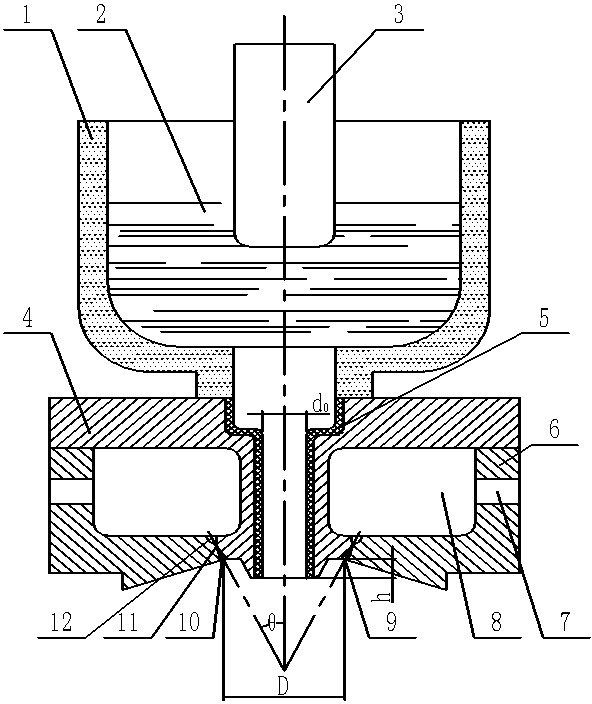
[0017] Specific Embodiment 1: This embodiment describes a supersonic atomizer for preparing iron-based spherical metal powder by using the crucible gas atomization method. The supersonic atomizer includes a crucible 1, a plunger 3, an upper Cover 4, catheter tube 5, lower cover 6, air inlet 7, air cavity 8 and laval type annular seam 9;

[0018] The upper cover 4 is provided with a central shoulder hole, the catheter 5 is installed in the central shoulder hole, the lower part of the upper cover 4 is provided with a lower cover 6, the upper cover 4 and the lower cover 6 is sealed and connected, the space between the upper cover 4 and the lower cover 6 forms an air cavity 8, and the side of the lower cover 6 is provided with an air inlet 7 communicating with the air cavity 8; A Laval-shaped annular seam 9 is formed between the inner sides, and the Laval-shaped annular seam 9 is coaxial with the central shoulder hole of the upper cover 4;

[0019] The upper end surface of the up...

specific Embodiment approach 2

[0020] Specific embodiment two: a supersonic atomizer for preparing iron-based spherical metal powder by crucible gas atomization method described in specific embodiment one, between the upper cover 4 and the lower cover 6 and between the crucible 1 and the Sealing rings are used to seal between the upper covers 4, and bolts are used to connect them respectively.

specific Embodiment approach 3

[0021] Embodiment 3: Embodiment 1 is a supersonic atomizer for preparing iron-based spherical metal powder by crucible gas atomization method, and the catheter 5 is made of graphite or ceramics.


PUM

PropertyMeasurementUnit
diameteraaaaaaaaaa
diameteraaaaaaaaaa

Abstract

The invention discloses a supersonic atomizer for preparing iron-based spherical metal powder through a crucible gas atomization method, and relates to the field of metal powder material preparation.The supersonic atomizer comprises a crucible, a plunger, an upper cover, a liquid guide pipe, a lower cover, gas feeding holes, a gas cavity and a Laval type circular seam; the liquid guide pipe is installed at the center of the upper cover, and the lower cover is arranged under the upper cover; the two gas feeding holes are oppositely formed in the side face of the lower cover; the gas cavity isdefined by the upper cover and the lower cover in a sealed mode and communicates with the upper cover and the lower cover; the Laval type circular seam formed by the upper cover and the lower cover together with the main axis of the atomizer as the center is arranged; and the crucible is filled with molten metal, and after the plunger is removed, the molten metal enters the atomizer through the liquid guide pipe to be atomized by gas flow sprayed out of the Laval type circular seam. The supersonic atomizer has the advantages that the gas flow is uniform and consistent, the turbulence scale issmall, and no impact wave exists in the flow field.

Description

technical field [0001] The invention relates to the field of metal powder material preparation, in particular to a supersonic atomizer for preparing iron-based spherical metal powder by using a crucible gas atomization method. Background technique [0002] In the industry of preparing metal powders, gas atomization technology has become one of the main methods to produce high-performance metal powders. The preparation of ultrafine spherical metal powder by gas atomization has many attractive characteristics, for example, it can effectively reduce the segregation of alloy components, and obtain alloy powder with fine microstructure and uniform composition. In addition, powders with non-equilibrium structures such as amorphous, quasicrystalline, microcrystalline or supersaturated solid solutions can be obtained by controlling the condensation rate, which are widely used in metal powder catalysts for synthetic diamonds, microelectronic welding, metal matrix composites, magnetic...

Claims


Application Information

Patent Timeline
Patent Type & Authority Applications(China)
IPC IPC(8): B22F9/08
CPCB22F9/082B22F2009/088
Inventor 不公告发明人
Owner 安徽哈特三维科技有限公司
Why Eureka
Try Eureka