
Ball cage holder broaching clamp

A cage and cage seat technology, which is applied to broaching machines, broaching machines, manufacturing tools, etc., can solve the problems of difficulty in ensuring accurate rotation angles, substandard products, and inconvenient placement of ball cage cages, so as to avoid uncertainty. sexual effect

Inactive Publication Date: 2018-08-24
安徽凯富机械部件有限公司
View PDF0 Cites 0 Cited by
  • Summary
  • Abstract
  • Description
  • Claims
  • Application Information

AI Technical Summary

Problems solved by technology

[0002] The ball cage cage is a component of the constant velocity universal joint, and its side wall is evenly arranged with a plurality of window holes. In the prior art, after the window holes are punched by a punching machine, the window holes need to be broached with a broaching machine For processing, since there are multiple window holes arranged on the side wall of the ball cage cage, when the hole is drawn, the broach pulls one hole in turn, which requires the worker to rotate the ball cage cage by about 60° after each hole is pulled, and the worker It is difficult to ensure the accuracy of the rotation angle by manual rotation, which will lead to large processing errors. If there is a mistake, it is easy to produce unqualified products; Hand injury; on some equipment, the handle fixedly connected to the cage seat is used to control the rotation. Although it avoids potential safety hazards, there is still the problem of inaccurate angle rotation. In addition, the setting of the handle is very inconvenient for the placement of the ball cage cage

Method used


Image

  • Ball cage holder broaching clamp
  • Ball cage holder broaching clamp

Examples


Embodiment Construction

[0011] Specific embodiments of the present invention will be described in detail below in conjunction with the accompanying drawings.

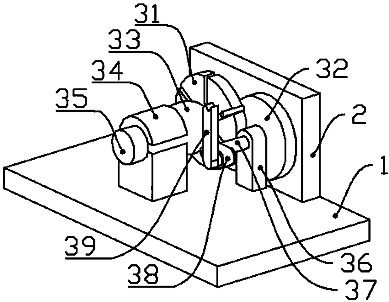
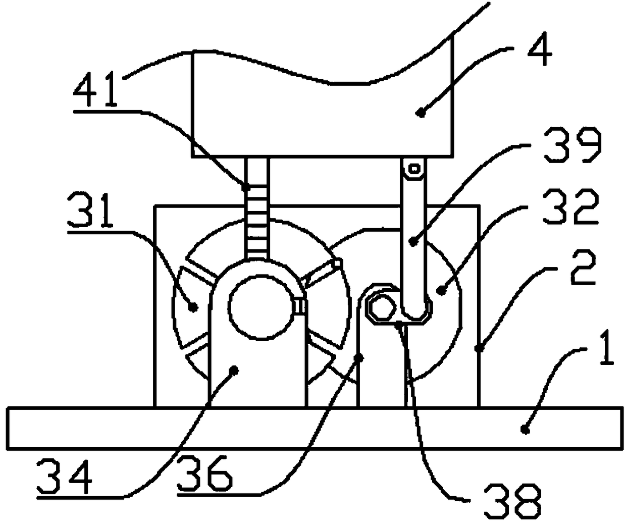
[0012] Such as figure 1 and figure 2 The jig for drawing the hole of a ball cage cage includes a base 1 for fixing on the workbench of a broaching machine, on which a back plate 2 is vertically fixed, and on the back plate 2 are pivotally fixed mating slaves. The movable sheave 31 and the driving pin wheel 32, the driven sheave 31 are fixedly connected to the ball cage holder seat 33, the ball cage holder seat 33 is connected to the cylindrical block 35 through a short axis, the driven sheave 31, the ball cage holder Seat 33, short shaft and cylinder stopper 35 are all coaxial, and described short shaft has a positioning block 34 that can be taken off; Described driving pin wheel 32 is connected to crank 38 through rotating shaft 36 on the side away from back plate 2, and rotating shaft 36 passes through support base 36, and one-way bearing...


PUM


Abstract

The invention discloses a ball cage holder broaching clamp, and belongs to the technical field of ball cage holder machining equipment. The problem that in the prior art, a ball cage holder needs to be manually rotated is solved. The clamp comprises a base fixed to a broaching machine worktable, a back plate is perpendicularly fixed to the base, a driven groove wheel and a driving pin wheel whichare matched are fixed to the back plate through a pivot shaft, the driven groove wheel is fixedly connected with a ball cage holder base, the ball cage holder base is connected with a cylindrical check block through a short shaft, the driven groove wheel, the ball cage holder base, the short shaft and the cylindrical check block are coaxial, the short shaft is sleeved with a positioning block capable of being taken down, the side, away from the back plate, of the driving pin wheel is connected with a crank through a rotating shaft, the rotating shaft penetrates a supporting base, and a one-waybearing is arranged between the rotating shaft and the supporting base; the crank is connected with a connecting rod, the connecting rod is movably connected with a broaching tool mounting base of abroaching machine, and rotation of the ball cage holder can be achieved automatically and precisely.

Description

technical field [0001] The invention belongs to the technical field of processing equipment for cage cages, and in particular relates to a hole-drawing jig for cage cages. Background technique [0002] The ball cage cage is a component of the constant velocity universal joint, and its side wall is evenly arranged with a plurality of window holes. In the prior art, after the window holes are punched by a punching machine, the window holes need to be broached with a broaching machine For processing, since there are multiple window holes arranged on the side wall of the ball cage cage, when the hole is drawn, the broach pulls one hole in turn, which requires the worker to rotate the ball cage cage by about 60° after each hole is pulled, and the worker It is difficult to ensure the accuracy of the rotation angle by manual rotation, which will lead to large processing errors. If there is a mistake, it is easy to produce unqualified products; Hand injury; on some equipment, the h...

Claims


Application Information

Patent Timeline
IPC IPC(8): B23D41/06B23D37/00
CPCB23D41/06B23D37/00
Inventor 潘云飞
Owner 安徽凯富机械部件有限公司
Features
  • Generate Ideas
  • Intellectual Property
  • Life Sciences
  • Materials
  • Tech Scout
  • Unparalleled Data Quality
  • Higher Quality Content
  • 60% Fewer Hallucinations
Learn More