Efficient switch-back type car dumper unloading system

A dumper and switchback technology, which is applied in the field of switchback dumper unloading system, can solve the problems of low operating efficiency, long working site, and wide land occupation, and achieve simple and efficient unloading system, automatic operation, and small footprint Effect

Active Publication Date: 2018-08-24
DALIAN HUARUI HEAVY IND GRP CO LTD
View PDF11 Cites 5 Cited by
  • Summary
  • Abstract
  • Description
  • Claims
  • Application Information

AI Technical Summary

Problems solved by technology

[0004] The disadvantage of the existing turn-back dumper unloading system is: for safety, during the shunting process, the condition for the steering machine to start from the wheel clamp is that the dumper returns to the zero position, and the car moving platform returns to the heavy car line in place
This makes the work efficiency low, because:
[0005] 1) The car moving platform transfers the empty car unloaded by the dumper on the heavy car line to the empty car line. After being pushed out by the cart machine, the operation process for the car moving platform to return to the heavy car line is too long;
[0006] 2) It takes too long for the steering machine to start towing the heavy vehicle and push the empty vehicle into the moving platform
[0007] In order to solve the shortcomings of the existing technology, the patented technology of ZL200520093436.6 discloses the "high-efficiency turn-back double-car dumper unloading system". The length of the gondola car is longer than that, and then the empty car puller is used to realize the relay operation on the heavy car line, resulting in too long work site, too wide area and high cost

Method used


Image

  • Efficient switch-back type car dumper unloading system
  • Efficient switch-back type car dumper unloading system
  • Efficient switch-back type car dumper unloading system

Examples


Embodiment Construction

[0041] The present invention will be further described below in conjunction with drawings and embodiments.

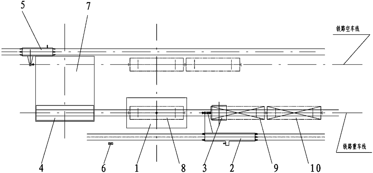
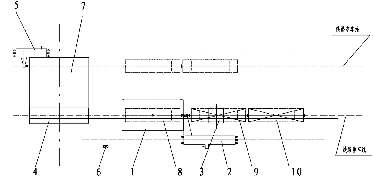
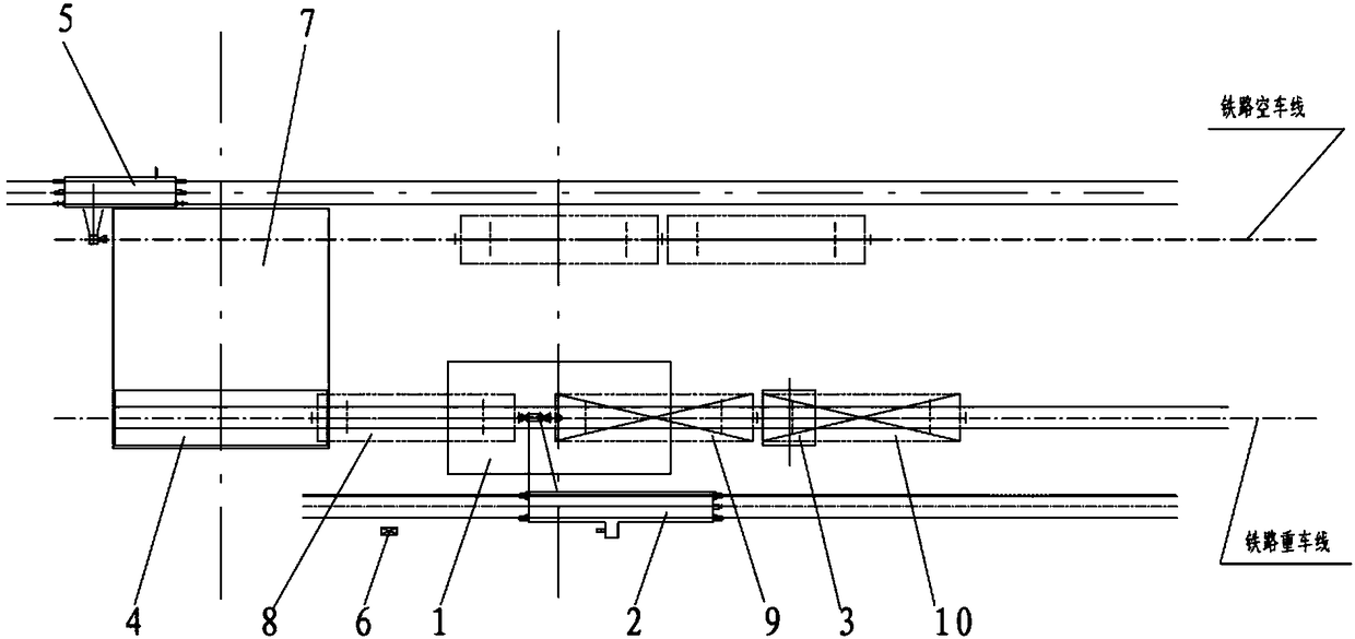
[0042] A high-efficiency turn-back dumper unloading system, including a dumper 1, a steering machine 2, a wheel gripper 3, a vehicle moving platform 4, a cart pusher 5, an auxiliary shunting machine 11, and 1# movable stoppers 12 and 2# Movable stopper 13 and shifting machine travel stopper 14, dumper 1 is located on railway heavy car line, and heavy car is the wagon row that goods are housed, and heavy car row is placed at the rear of dumper 1, and a part of railway heavy car line The railway empty car line is set on one side, and the shifter line is set on the other side. The shifter 2 is arranged on the shifter line, and is used to pull the heavy trains to move forward. The moving platform 4 is located in front of the dumper 1. Platform 4 moves between the railway heavy train line and the railway empty train line, and is used to move the unloaded empty train from the...


PUM


Abstract

An efficient switch-back type car dumper unloading system comprises a car dumper, a car puller, a wheel gripper, a transfer platform, a car pusher and car stops and further comprises an auxiliary shunting locomotive. The auxiliary shunting locomotive is arranged at one end of the transfer platform on the car puller line. The car stops comprise a first moving car stop, a second moving car stop anda car puller travel stop. The first moving car stop and the second moving car stop can be raised and laid flat, when being raised, the first moving car stop and the second moving car stop are the carstopping station, and when being laid flat, the first moving car stop and the second moving car stop are the passage station, and the first moving car stop and the second moving car stop are arrangedbetween a transfer platform foundation pit and the car dumper. The car puller travel stop is arranged at the final end of the travel of the car puller and located at the position where a big arm of the car puller just moves out the car dumper. The efficient switch-back type car dumper unloading system has the beneficial effects that the work travel of the car puller is shortened, the operation time of the car puller and the operation time of the auxiliary shunting locomotive coincide, and the operation efficiency is improved; the auxiliary shunting locomotive smoothly conducts round-trip operation between the transfer platform and the car dumper, the auxiliary shunting locomotive can be effectively prevented from going beyond the planned position, and the efficient switch-back type car dumper unloading system is easy and convenient to use, efficient, low in investment, small in occupation area and capable of achieving automatic operation.

Description

technical field [0001] The invention belongs to a transportation and unloading system for railway locomotives, in particular to a switchback type dumper unloading system, which is used to greatly improve the operating efficiency of the switchback dumper unloading system. Background technique [0002] In the prior art, the turn-back dumper unloading system is mainly composed of a dumper, a turner, a wheel gripper, a moving platform, a pusher, a travel stop of the turner, etc. On the line, heavy vehicles are trains loaded with goods. The heavy vehicles are placed behind the dumper. One side of the railway heavy vehicle line is the railway empty car line, and the other side is the dialing machine line. On the line, it is used to pull the heavy trains to move forward. The moving platform is located in front of the dumper. The moving platform moves between the heavy railway line and the empty railway line. When moving to the empty car line, the cart pusher is set on the side of ...

Claims


Application Information

Patent Timeline
Patent Type & Authority Applications(China)
IPC IPC(8): B65G67/48B65G67/54
CPCB65G67/48B65G67/54
Inventor 王金福王晓斌王鹏殷立龙
Owner DALIAN HUARUI HEAVY IND GRP CO LTD
Why Eureka
Try Eureka