Fully assembled light abutment and construction method thereof
What is Al technical title?
Al technical title is built by PatSnap Al team. It summarizes the technical point description of the patent document.
A fully-assembled and light-weight technology, which is applied in the direction of erecting/assembling bridges, bridges, bridge parts, etc., can solve the problems of large construction area, reduce component size, environmental pollution, etc., achieve the improvement of anti-knock performance and strengthen the bridge abutment Strength and the effect of reducing construction costs
Pending Publication Date: 2018-08-24
XIANGTAN UNIV
View PDF6 Cites 10 Cited by
Summary
Abstract
Description
Claims
Application Information
AI Technical Summary
This helps you quickly interpret patents by identifying the three key elements:
Problems solved by technology
Method used
Benefits of technology
Problems solved by technology
[0005] The technical problem to be solved by the present invention is to overcome the deficiencies of the prior art and provide a fully assembled light abutment and its construction method, which utilizes the characteristics of UHPC ultra-high compressive strength and ultra-high toughness to ensure the strength and stability of components On the premise of greatly reducing the component size, reducing the requirements for mechanical transportation and hoisting capacity in the assembly construction; prefabricating the large components of the abutment in blocks can avoid the quality problems caused by the hydration heat during the construction of large-volume concrete, and can effectively solve the traditional In the cast-in-place construction method of the abutment, there are problems such as slow progress, large construction area and serious environmental pollution, and the structural force is clear, the quality is easy to control, and the construction process is simple
Method used
Image
Click on the blue label to locate the original text in one second.
Reading with bidirectional positioning of images and text.
Examples
Embodiment Construction
[0042] In order to facilitate the understanding of the present invention, the present invention will be described more fully and in detail below in conjunction with the accompanying drawings and preferred embodiments, but the protection scope of the present invention is not limited to the following specific embodiments.
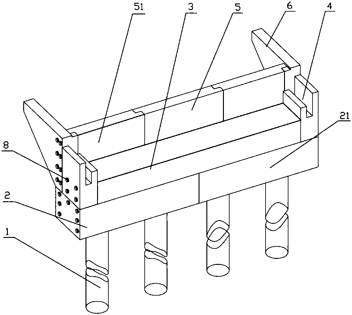
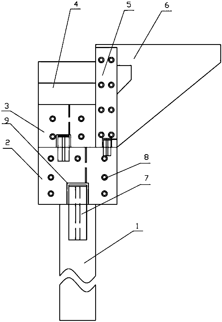
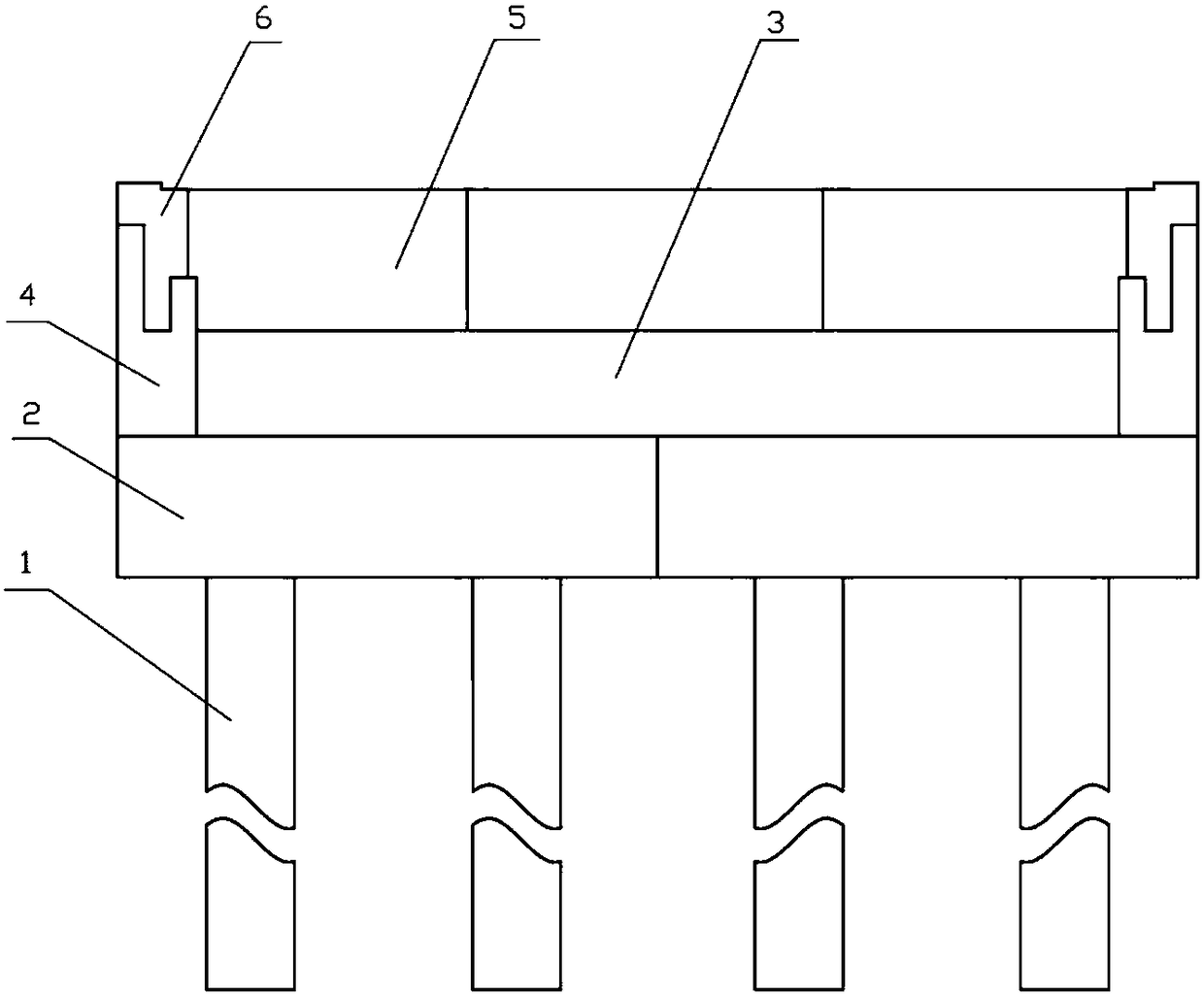
[0043] Such as Figure 1 to Figure 9 As shown, a fully assembled light-duty abutment includes a pile foundation 1, a cap 2 installed above the pile foundation 1, an abutment cap 3 installed above the cap 2, and an abutment cap 3 installed at the left and right ends of the abutment cap 3 and located at The double block 4 above the cap 2, the back wall corbel 5 and the ear wall 6 located on one side of the platform cap 3 and installed above the cap 2, the double stop 4 is connected with the back wall corbel 5, and the cap 2 , platform cap 3, double block 4, back wall corbel 5 and ear wall 6 are UHPC prefabricated components with internal reinforcement cages, pi...
PUM
Abstract
The invention discloses a fully assembled light abutment. The abutment comprises a pile foundation, a cushion cap, an abutment cap, double baffle blocks, a back wall bracket and a wing wall, the double baffle blocks are connected with the back wall bracket and installed on the cushion cap, the cushion cap, the abutment cap, the double baffle blocks, the back wall bracket and the wing wall are UHPCprefabricated components internally provided with reinforcement cages, the pile foundation is an NC prefabricated component or a UHPC prefabricated component internally provided with reinforcement cages, the cushion cap is connected with the pile foundation through an H-shaped steel plate with a sealing end cover plate, the abutment cap, the wing wall and the back wall bracket are connected withthe cushion cap through H-shaped steel plates with sealing end cover plates, the double baffle blocks are in tensile connection with the abutment cap through prestress reinforcing bars, and the back wall bracket is in tensile connection with the wing wall through prestress reinforcing bars; the construction method of the structure is included. According to the fully assembled light abutment, a fully assembled structure is adopted, the abutment has the advantages of being fast in construction speed, simple in process, easy to control in engineering project quality, less in occupation space of construction sites and the like, and the existing problem of slow construction process, the quality problem brought by hydration heat when large volume concrete construction is conducted, the problemsof large occupation space and environmental pollution and the like of traditional abutments can be effectively solved.
Description
technical field [0001] The invention relates to a bridge component and a construction method thereof, in particular to a fully assembled light abutment and a construction method thereof. Background technique [0002] At present, the bridge substructure in our country mainly adopts the construction method of cast-in-place. The construction period of on-site pouring is long, the amount of labor is large, the on-site pouring is affected by the weather, the construction quality is not easy to guarantee, and the construction covers a large area, and the on-site pouring may cause a lot of waste of concrete due to long-distance transportation of concrete and the professional quality of construction personnel. , causing a large number of direct economic losses, and serious pollution to the surrounding area during the construction process. In order to overcome these unfavorable factors, it is an urgent problem to be solved in bridge construction to find a construction speed block an...
Claims
Application Information
Patent Timeline
Application Date:The date an application was filed.
Publication Date:The date a patent or application was officially published.
First Publication Date:The earliest publication date of a patent with the same application number.
Issue Date:Publication date of the patent grant document.
PCT Entry Date:The Entry date of PCT National Phase.
Estimated Expiry Date:The statutory expiry date of a patent right according to the Patent Law, and it is the longest term of protection that the patent right can achieve without the termination of the patent right due to other reasons(Term extension factor has been taken into account ).
Invalid Date:Actual expiry date is based on effective date or publication date of legal transaction data of invalid patent.