Correction method for eliminating non-linearity of semiconductor laser frequency modulation interference signal

A technology of interference signal and correction method, applied in the direction of optical devices, instruments, measuring devices, etc., can solve the problems of limited locking range of photoelectric phase-locked loop, limited range of linear frequency modulation, low linear frequency modulation accuracy, etc., and achieves easy implementation and transformation Easier and better measurement accuracy

Active Publication Date: 2018-08-24
XIAN TECH UNIV
View PDF5 Cites 10 Cited by
  • Summary
  • Abstract
  • Description
  • Claims
  • Application Information

AI Technical Summary

Problems solved by technology

The open-loop correction method has a simple hardware system structure and is easy to implement, but there is a problem of low linear frequency modulation accuracy
The closed-loop correction method can achieve high-precision nonlinear correction, but the system is complex, and because the locking range of the photoelectric phase-locked loop is limited, the chirp range is greatly limited

Method used


Image

  • Correction method for eliminating non-linearity of semiconductor laser frequency modulation interference signal
  • Correction method for eliminating non-linearity of semiconductor laser frequency modulation interference signal
  • Correction method for eliminating non-linearity of semiconductor laser frequency modulation interference signal

Examples


Embodiment 1

[0051] A correction method for eliminating the nonlinearity of a semiconductor laser frequency modulation interference signal, comprising the steps of:

[0052] Step 1: Assume that the mathematical expression of the ideal FM continuous wave interference beat frequency signal I(t) is:

[0053]

[0054] Here, T=1 / v b , determined by the optical path difference between the two frequency-modulated lasers.

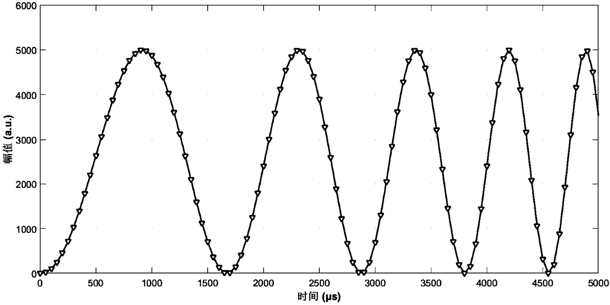
[0055] When the laser light source has nonlinear frequency modulation, the frequency of the frequency modulation interference beat frequency signal also changes accordingly, so there is nonlinearity. Use the photodetector to convert the semiconductor laser frequency modulation interference optical signal into an analog electrical signal, and then filter, amplify and AD convert, the obtained beat frequency signal can be expressed by a quadratic polynomial, and the mathematical expression of the beat frequency signal at this time is:

[0056]

[0057] Here, I 0 is the si...

Embodiment 2

[0067] A correction method for eliminating the nonlinearity of a semiconductor laser frequency modulation interference signal, comprising the steps of:

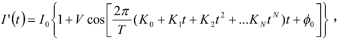
[0068] Step 1: same as embodiment 1, obtain beat frequency signal mathematical expression as:

[0069]

[0070] Step 2: In this embodiment, the time-domain transformation formula can use third-order and higher-order N-order polynomials, and the corresponding modulation transformation coefficient is K 0 、K 1 ,...,K N , for N-order polynomials of third order and above, take the time position t corresponding to N+2 adjacent extreme points 1 , t 2 ,...,t N+2 , and establish the modulation transform coefficient K 0 、K 1 ,...,K N The N+1 linear equation system of

[0071]

[0072] Solving this system of linear equations, we can get K 0 、K 1 ,...,K N N+1 modulation transformation coefficients,

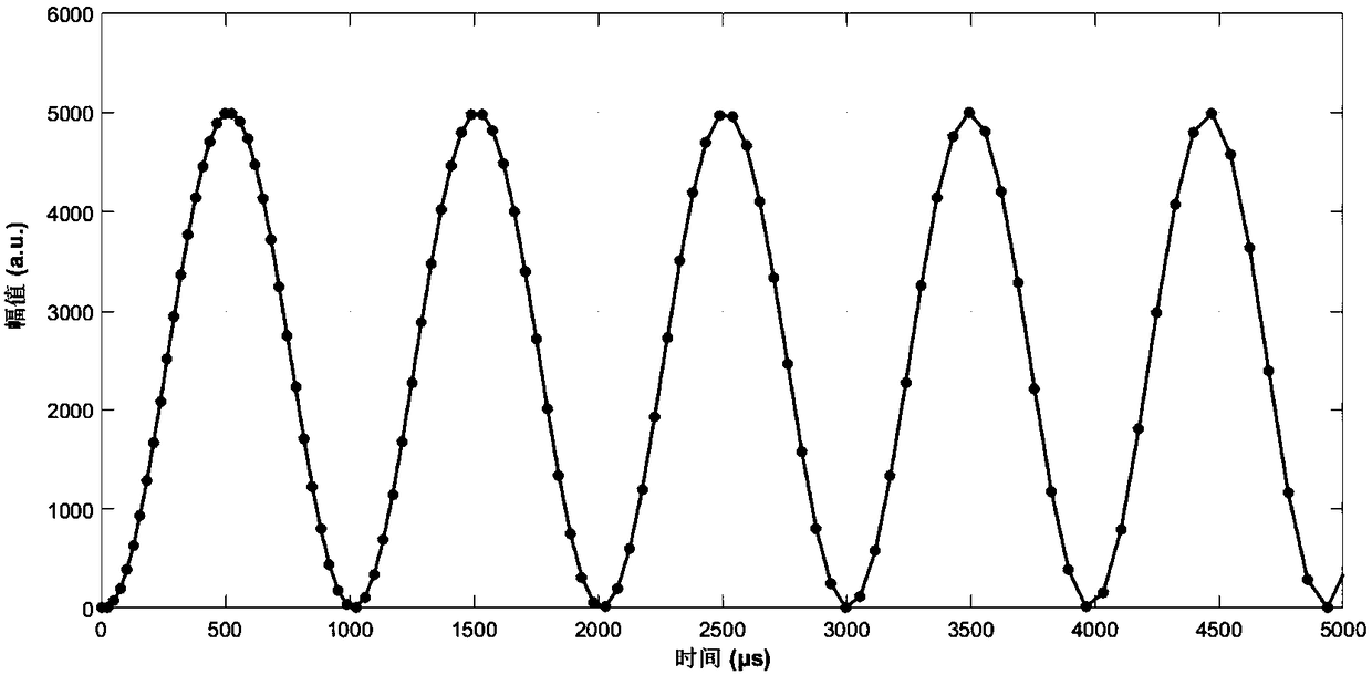
[0073] Step 3: Carry out time-domain transformation to the measured beat frequency signal according to the obtained modul...

Embodiment 3

[0075] A correction method for eliminating the nonlinearity of a semiconductor laser frequency modulation interference signal, comprising the steps of:

[0076] Step 1: same as embodiment 1, obtain beat frequency signal mathematical expression as:

[0077]

[0078] Step 2: In this embodiment, the time position t corresponding to N+2 extreme points can be selected by jumping 1 , t 2 ,...,t N+2 , that is, any two extreme points selected in sequence may not be adjacent, such as t i and t i+1 There are k-1 extreme points between the corresponding extreme points, then in the N+1 linear equation system, the corresponding modulation transformation coefficient K 0 、K 1 ,...,K N The linear equation for becomes:

[0079]

[0080] Other about the modulation transformation coefficient K 0 、K 1 ,...,K N The linear equation of , and so on, solve the corresponding linear equations to get K 0 、K 1 ,...,K N N+1 modulation transformation coefficients;

[0081] Step 3, accor...


PUM


Abstract

The invention relates to the technical field of semiconductor laser frequency modulation interference sensing and measurement, and specifically relates to a correction method for eliminating non-linearity of semiconductor laser frequency modulation interference signals. The correction method for eliminating non-linearity of semiconductor laser frequency modulation interference signals comprises: establishing a second-order or higher polynomial time-domain transform relation, for beat-frequency interference signals of a frequency modulated continuous wave laser interference measuring system, extracting time positions of a plurality of adjacent extreme points, establishing a multiple linear equation set with respect to a modulated transformation coefficient and solving to obtain an actual value of the modulated transformation coefficient, brining the actual value into the established second-order or higher polynomial time-domain transform relation, transforming the actually measured beat-frequency signals, so as to realize correction of semiconductor laser frequency modulation continuous wave interference signal non-linearity. The method can be used for various frequency modulation continuous wave interference measuring systems based on semiconductor lasers, and improves measuring precision of an optical frequency modulation continuous wave interference measuring system which uses the semiconductor laser as an emitting light source.

Description

technical field [0001] The invention relates to the technical field of semiconductor laser frequency modulation interference sensing and measurement, in particular to a method for correcting nonlinearity of semiconductor laser frequency modulation interference signals. Background technique [0002] Displacement, stress, and temperature sensors based on optical frequency-modulated continuous wave (FMCW) interferometry, as well as fiber optic gyroscopes, all require the use of a coherent light source with continuous linear modulation of frequency. At present, single-mode semiconductor lasers are considered to be the most suitable frequency-modulated coherent light sources, because the frequency modulation method of semiconductor lasers is relatively simple, and frequency modulation can be realized by directly modulating the driving current. However, there is no linear relationship between the driving current and the output frequency of the semiconductor laser, which makes the ...

Claims


Application Information

Patent Timeline
Patent Type & Authority Applications(China)
IPC IPC(8): G01B9/02
CPCG01B9/02074
Inventor 郑刚高明刘卫国陈海滨张雄星王伟郭峰
Owner XIAN TECH UNIV
Why Eureka
Try Eureka