Visual test device for liquid drop collision high-temperature wall surface and heating system thereof

A technology of high-temperature wall surface and droplet collision, which is used in measurement devices, engine testing, machine/structural component testing, etc. to achieve effective acquisition, small heat loss, and uniform heating

Inactive Publication Date: 2018-08-24
BEIJING INSTITUTE OF TECHNOLOGYGY
View PDF6 Cites 7 Cited by
  • Summary
  • Abstract
  • Description
  • Claims
  • Application Information

AI Technical Summary

Problems solved by technology

[0004] At present, there is no liquid collision solution that can combine the advantages of metal walls and glass walls, and can clearly observe the droplet shape changes during the collision process at different temperatures, thus helping to better study the phenomenon of droplet collision

Method used


Image

  • Visual test device for liquid drop collision high-temperature wall surface and heating system thereof

Examples


Embodiment Construction

[0020] The present invention will be described in detail below in conjunction with the accompanying drawings.

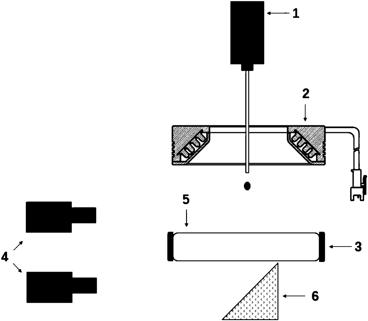
[0021] Firstly, the present invention provides a visual test device with a glass wall heating device for droplet impact on a high-temperature wall. The visual test device includes: a droplet injection system, a glass wall, a heating system and a visualization system.

[0022] Such as figure 1 As shown, the droplet injection system is a droplet injector, which is set above the glass wall, and its height can be adjusted to control the falling height of the droplet and thus the velocity of the droplet hitting the wall.

[0023] The heating system includes a heating controller and a heat source, wherein the heat source is an annular heating heat source, which is in contact with the glass wall, and the area of ​​the glass wall surrounded by the annular heating heat source is the droplet collision experiment area. Due to the ring shape, one can make The glass wall is even...


PUM


Abstract

The invention discloses a visual test device for a liquid drop collision high-temperature wall surface. The visual test device comprises a liquid drop injection system, a glass wall surface and a visual system. The device further comprises a heating system. The heating heat source of the heating system is annular. The annular heating heat source is in contact with a glass wall surface. The glass wall surface area of the annular heating heat source is adopted as a liquid drop test area on the wall surface. Matched with a circumferential distribution type light source, the visual system can be used for shooting the liquid drop wall collision test process from the bottom of the glass wall surface or at any angle of the upper part of the glass wall surface. The invention further discloses a heating system applied to the above test device. The visual test device provided by the invention adopts the novel glass wall surface heating method, so that the change of liquid drops during the wall collision process at different temperatures can be clearly observed. The phenomenon of liquid drop wall collision can be better and more comprehensively studied.

Description

technical field [0001] The invention relates to a visual testing device and a heating system for liquid droplets colliding with a high-temperature wall. Background technique [0002] For in-cylinder direct injection engines, with the development of small structure, high supercharging and high injection pressure, the fuel is easy to hit and adhere to the cylinder wall and piston wall to form a wall oil film due to the limited evaporation time, etc. Cause real fuel loss and reduce engine economy. At the same time, because the oil film evaporation in the cycle is very small, it will also affect the formation of the mixture gas in the subsequent working cycle of the engine. With the continuous accumulation of the wall oil film, a fuel-rich area will be formed locally, resulting in a significant increase in the emission of soot particles and the formation of carbon deposits. Carbon deposits are equivalent to hot spots one by one. When the temperature in the cylinder is high, it...

Claims


Application Information

Patent Timeline
Patent Type & Authority Applications(China)
IPC IPC(8): G01M15/00G01M15/02
CPCG01M15/00G01M15/02
Inventor 吴晗王利利刘福水岑春泽汤成龙李佳峰
Owner BEIJING INSTITUTE OF TECHNOLOGYGY
Why Eureka
Try Eureka