
Surface defect detecting device based on laser diffuse scattering

A defect detection and diffuse scattering technology, which is applied in the directions of measuring devices, optical testing flaws/defects, color/spectral characteristics measurement, etc., can solve the problems of slow resolution and detection speed, inability to meet online detection, and small quantity, and achieve detection The effect of fast speed, slow detection speed and high accuracy

Pending Publication Date: 2018-08-24
杭州智谷精工有限公司
View PDF8 Cites 5 Cited by
  • Summary
  • Abstract
  • Description
  • Claims
  • Application Information

AI Technical Summary

Problems solved by technology

[0003] At present, in addition to manual detection of defects on smooth surfaces, there are still some mechanized detection methods. The most representative and practical method is the optical detection method based on Machine Vision (machine vision), which can simultaneously detect And determine the type, size and other parameters of the defect, but the disadvantage is that this method needs to scan the surface to be tested, and according to experience, most of the surface to be tested has no defects, even if there are, the number is very small, and based on The inspection method of machine vision must carry out indiscriminate inspection on the entire surface. Therefore, regardless of whether the tested surface is defective or not, the inspection time is the same, and most of the time is spent on image acquisition and processing of the non-defective surface. The resolution and detection speed of this kind of indiscriminate detection are relatively slow, and the detection and analysis time usually ranges from tens of seconds to several minutes, which cannot meet the needs of high-speed and efficient online detection.

Method used


Image

  • Surface defect detecting device based on laser diffuse scattering
  • Surface defect detecting device based on laser diffuse scattering
  • Surface defect detecting device based on laser diffuse scattering

Examples


Embodiment Construction

[0018] The present invention will be further described below in conjunction with the accompanying drawings and specific embodiments (embodiments). The specific embodiments described here are only used to explain the present invention, but not as a basis for limiting the present invention.

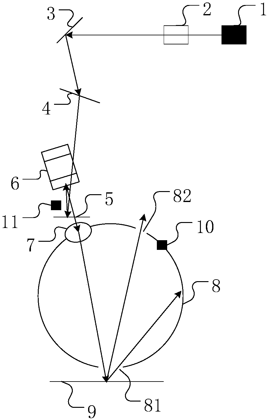
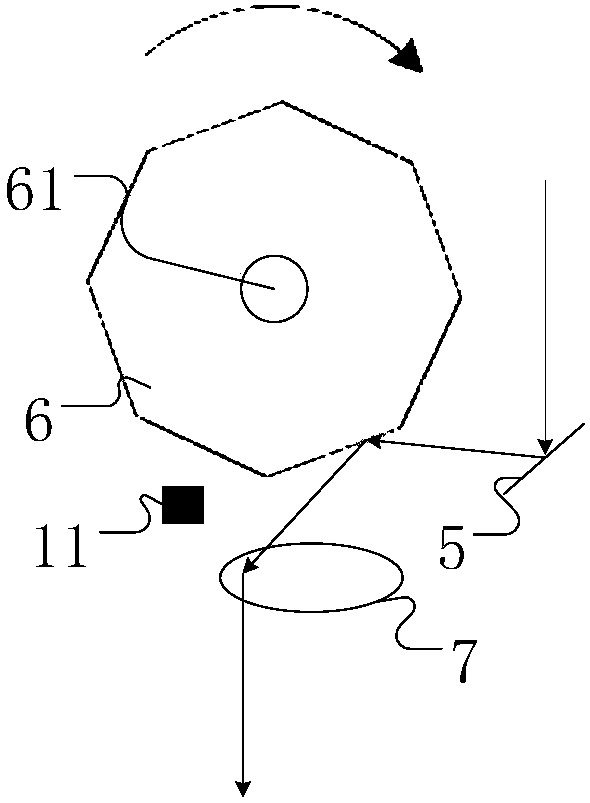
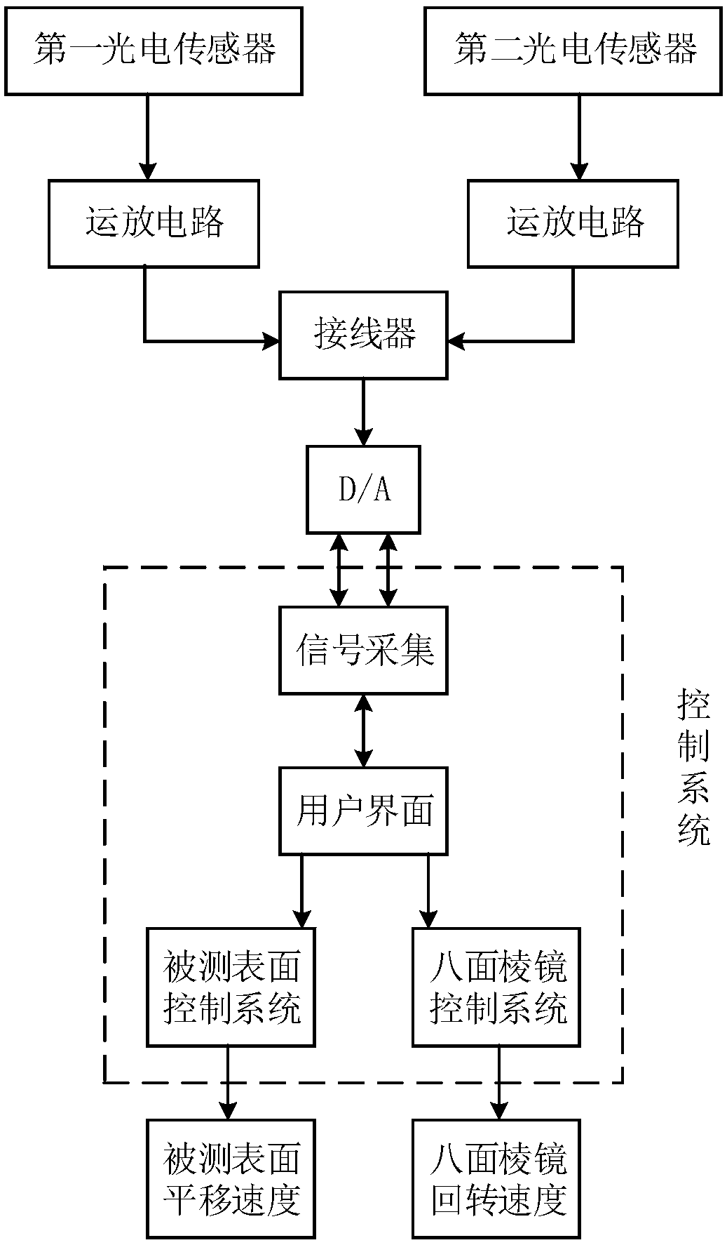
[0019] see figure 1 , the surface defect detection device based on diffuse laser scattering of the present invention includes a laser 1, a beam expander 2, a first adjustment mirror 3, a second adjustment mirror 4, a third adjustment mirror 5, an octahedral prism 6, and a telecentric scanning lens 7. The inner integrating sphere 8, the measured surface 9 and the first photoelectric sensor 10; the beam expander 2 is used to expand the diameter of the laser beam emitted by the laser 1 and output it as a parallel beam; the first adjusting mirror 3 , the second adjustment mirror 4 and the third adjustment mirror 5 are arranged behind the beam expander 2 in order to adjust the direction of the l...


PUM


Abstract

The invention relates to a surface defect detecting device based on laser diffuse scattering. The device comprises a laser, a beam expander, a first adjusting mirror, a second adjusting mirror, a third adjusting mirror, an octagonal prism, a telecentric scanning lens, an inner integrating sphere, a measured surface and a first photoelectric sensor; the first adjusting mirror, the second adjustingmirror and the third adjusting mirror are sequentially disposed behind the beam expander, the octagonal prism is disposed above the third adjusting mirror, the center of the octagonal prism is provided with a driving shaft, a first opening is formed in the bottom of the inner integrating sphere, a second opening is formed in the upper portion, and the inside of the integrating sphere is provided with the first photoelectric sensor. The surface defect detecting device based on laser diffuse scattering adopts laser scanning and a scattering detecting technology, can detect a smooth surface in ashort time and determine the specific location of a defect, can perform preliminary processing on a defect image, achieves visual operation, and has the advantages of fast scanning speed, high detection efficiency, high precision and the like.

Description

technical field [0001] The invention relates to the technical field of laser detection, in particular to a surface defect detection device based on diffuse laser scattering. Background technique [0002] With the advancement of science and technology, many tedious, complicated and repetitive tasks have gradually developed from manual operations to mechanized operations, which can avoid operator errors caused by certain factors in manual operations, and save operators from complicated work. Liberation can also improve work efficiency and accuracy, and save labor costs. [0003] At present, in addition to manual detection of defects on smooth surfaces, there are still some mechanized detection methods. The most representative and practical method is the optical detection method based on Machine Vision (machine vision), which can simultaneously detect And determine the type, size and other parameters of the defect, but the disadvantage is that this method needs to scan the sur...

Claims


Application Information

Patent Timeline
Patent Type & Authority Applications(China)
IPC IPC(8): G01N21/39G01N21/95G01N21/88
CPCG01N21/39G01N21/8806G01N21/95G01N2021/8822
Inventor 袁巨龙肖绍尊
Owner 杭州智谷精工有限公司
Learn More