
Control method and system of controllable arrester

A control method and control system technology, applied in the field of controllable arrester control, can solve the problems of failure to design the closing control strategy of the blocking line switch, reducing the switching reliability of the line operating condition, and failing to optimize the design of the delay, etc. Achieve the effect of simple and reliable algorithm implementation, reduce manufacturing difficulty, and reduce operating overvoltage

Active Publication Date: 2018-08-24
NR ELECTRIC CO LTD +2
View PDF5 Cites 5 Cited by
  • Summary
  • Abstract
  • Description
  • Claims
  • Application Information

AI Technical Summary

Problems solved by technology

[0007] 1) There are many connections between the control system and the control and protection system of the original line switchgear in the station, which will reduce the reliability of line operating condition switching in the field of power system
[0008] 2) The delay between the operation of cutting off the controllable part and the closing operation of the line switch has not been optimally designed
[0009] 3) When the operation of removing the controllable part fails abnormally, the control strategy for closing the circuit breaker is not designed
[0010] 4) The control of the controllable part requires the intervention of the operator, which reduces the reliability of the operation

Method used


Image

  • Control method and system of controllable arrester
  • Control method and system of controllable arrester
  • Control method and system of controllable arrester

Examples


Embodiment Construction

[0050] The present invention is explained in detail below in conjunction with examples.

[0051] figure 1 Indicate the structure and installation position of the controllable arrester. Taking Station A as an example, the controllable arrester is composed of a fixed part M11 and a controllable part M12. Both ends of the controllable part are connected to the control switch K1. Install controllable surge arresters, install controllable surge arresters at both ends of the UHV transmission line, and configure a set of surge arrester control systems on each side. The control system of the controllable arrester mainly operates the controllable part of the arrester in parallel with the control switch K1. When the control switch K1 is closed, the controllable part M12 exits, and when the control switch K1 opens, the controllable part M12 enters.

[0052] The present invention proposes a control method for automatically controlling the parallel connection switch of the controllable part...


PUM


Abstract

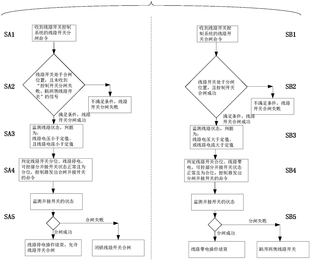
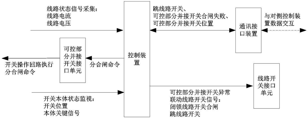
The invention provides a control method of a controllable arrester. The controllable arrester is composed of a controllable part and a fixed part, wherein the controllable part and the fixed part areconnected in series. The controllable part is switched through a control switch connected with both ends thereof. When the control switch is closed, the controllable part drops out. When the control switch is opened, the controllable part is in. The control method comprises the steps that line electrification detection is carried out; the controllable part is controlled to be connected in parallelwith opening and closing of the control switch according to the detection result, so that in and out of the controllable part automatically cooperate with opening and closing of a line switch; at thesame time, the running state of the control switch connected in parallel with the controllable part is monitored in real time; and when the control switch is abnormal, the line switch is operated inlinkage. The invention further proposes a control system of the controllable arrester. According to the invention, the control system of the controllable part of the controllable arrester and the control system of the line switch can be decoupled; the logic reliability of the controllable part in closing of the lock line switch is improved; and the intervention of operating personnel is reduced.

Description

technical field [0001] The invention belongs to the field of high voltage and extra high voltage power transmission, and in particular relates to a control method and system of a controllable lightning arrester. Background technique [0002] The controllable surge arrester is an operating overvoltage flexible limiting device that adapts to changes in operating conditions. The arrester body is composed of a controllable part and a fixed part in series. Both ends of the controllable part are connected to control switches in parallel. The control switch can be a power electronic switch , The bypass circuit breaker is realized, the control switch is closed and the controllable part is withdrawn, and the control switch is opened and the controllable part is put into operation. This method is combined with the method of installing a conventional lightning arrester in the middle of the line, which can deeply reduce the operating overvoltage and cancel the closing resistance of the ...

Claims


Application Information

Patent Timeline
Patent Type & Authority Applications(China)
IPC IPC(8): H02H7/00H02H1/00H02J13/00H02J3/00
CPCH02H1/0069H02H7/008H02J3/00H02J13/00019Y02E60/00Y04S10/20
Inventor 葛健张磊张春合陈维江葛栋陈秀娟
Owner NR ELECTRIC CO LTD
Learn More