Multibus IO-LINK master station supporting device and method

An IO-LINK and multi-bus technology, applied in the field of communication, can solve the problems of inconvenient use and achieve the effect of convenient operation

Pending Publication Date: 2018-08-24
SANMING UNIV
View PDF17 Cites 8 Cited by
  • Summary
  • Abstract
  • Description
  • Claims
  • Application Information

AI Technical Summary

Problems solved by technology

This method is limited by the installation location and space of the equipment,

Method used


Image

  • Multibus IO-LINK master station supporting device and method
  • Multibus IO-LINK master station supporting device and method
  • Multibus IO-LINK master station supporting device and method

Examples


no. 1 example

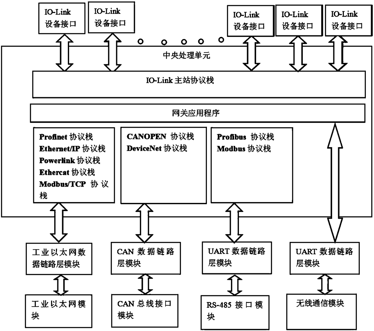
[0034] see figure 1 , figure 1 It is a schematic structural diagram of a device supporting a multi-bus IO-LINK master station provided by the present invention. The purpose of the present invention is to solve the multi-bus coexistence problem faced by the current IO-LINK master station, provide an IO-LINK master station device supporting multi-bus, and provide a smooth transition from existing IO equipment to IO-LINK equipment. , this solution can retain most of the technical advantages of IO-LINK in diagnosis, configuration and installation. And the wireless communication is used on the IO-LINK master station to realize the diagnosis and configuration of the equipment can be completed flexibly with the mobile handheld device.

[0035]The embodiment of the present invention provides a device supporting a multi-bus IO-LINK master station, which specifically includes: an industrial Ethernet module, a CAN bus interface module, an RS485 communication module, a physical layer co...

no. 2 example

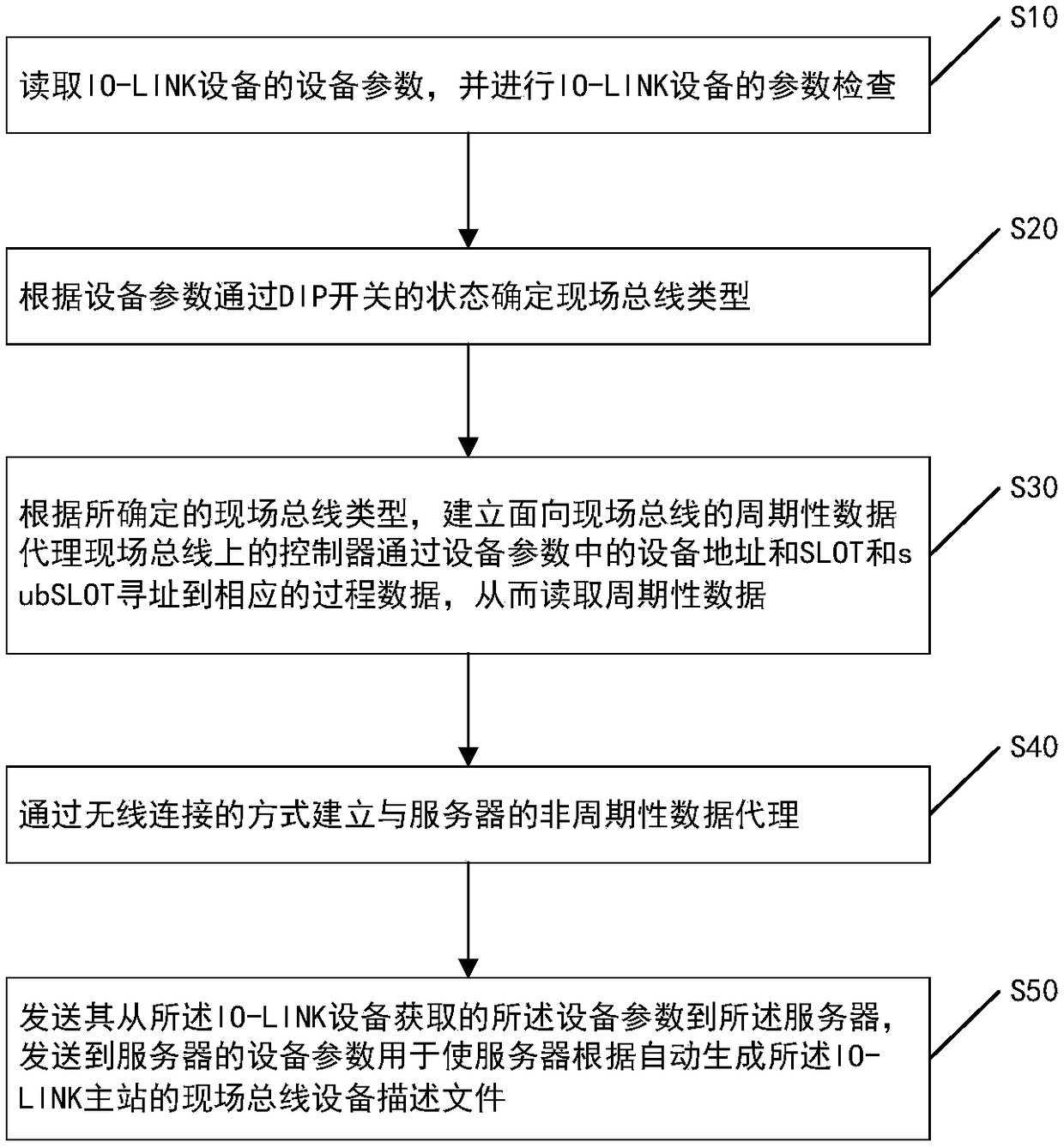
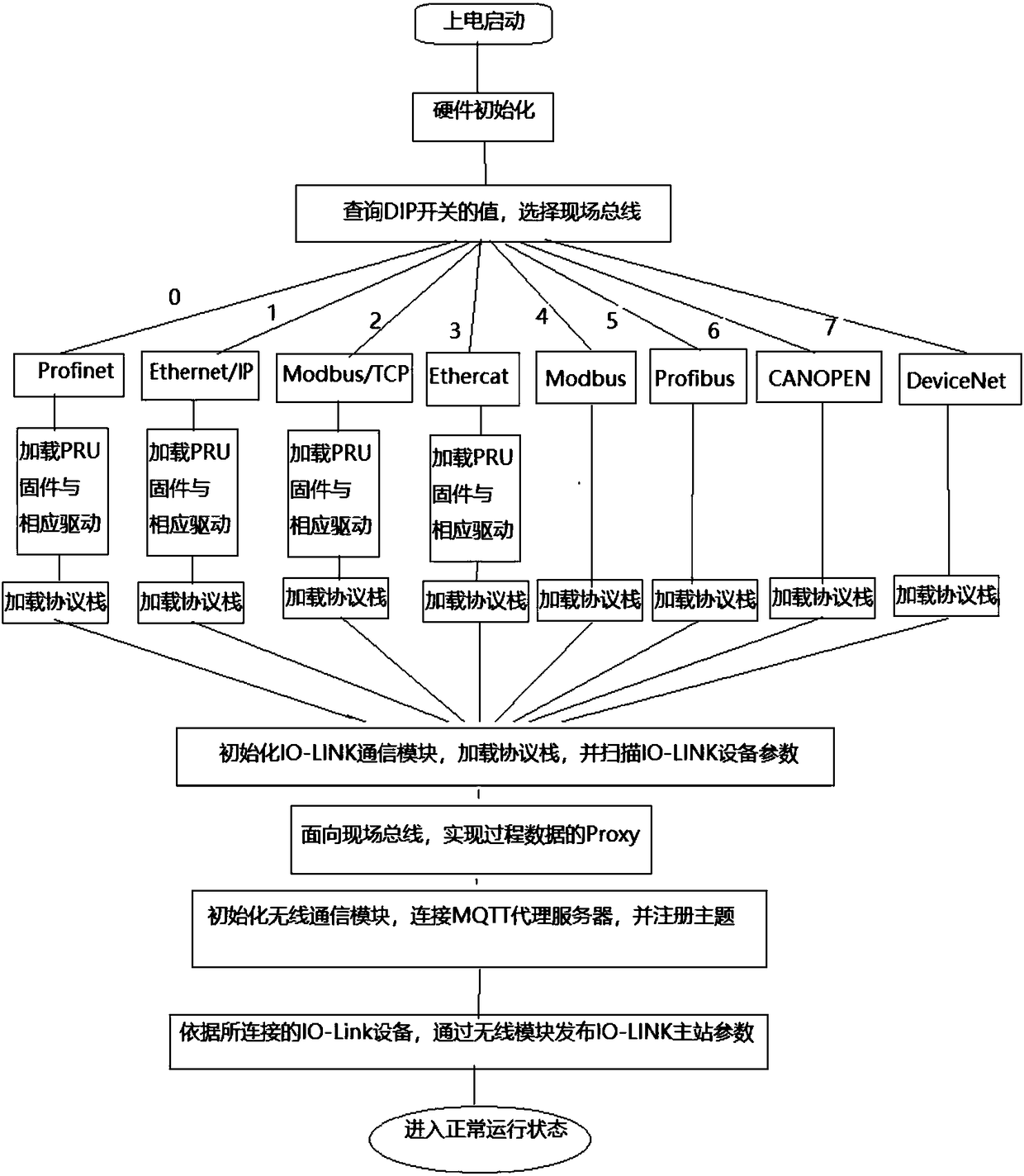
[0047] On the basis of the first embodiment, refer to Figure 2 to Figure 4 , figure 2 It is a schematic flowchart of a method for supporting a multi-bus IO-LINK master station provided by the present invention, image 3 It is a schematic diagram of the start-up process of a multi-bus IO-LINK master station provided by the present invention, Figure 4 It is a schematic diagram of the integrated structure of a multi-bus IO-LINK master station provided by the present invention. A method for an IO-LINK master station supporting multiple buses, said method consisting of

[0048] IO-LINK master station execution, including:

[0049] S10, reading the device parameters of the IO-LINK device, and checking the parameters of the IO-LINK device.

[0050] see image 3 , when the power-on startup program starts, the hardware is initialized, the IO-LINK communication module is initialized, the IO-LINK protocol stack is loaded, and the IO-LINK port is scanned, the parameters of the IO-...


PUM


Abstract

The embodiment of the invention discloses a multibus IO-LINK master station supporting device. The device comprises an industrial Ethernet module, a CAN bus interface module, an RS485 communication module, an IO-LINK master station physical layer communication module, a central processing module and a wireless communication module. The industrial Ethernet module is connected with the central processing module in an MII interface mode. The CAN bus interface module is connected with the central processing module through a UART interface. The RS485 communication module is connected with the central processing module through the UART interface. The wireless communication module is connected with the central processing module through the UART interface. Periodic data and aperiodic data are processed separately. Under the condition of not changing existing upper computer control hardware architecture, IO layer devices are smoothly upgraded as IO-LINK devices. Moreover, most advantages of anIO-LINK technology are reserved.

Description

technical field [0001] The invention relates to the field of communication technology, in particular to an IO-LINK master station device and method supporting multiple buses. Background technique [0002] IO-LINK is a new IO-level communication technology that has emerged in recent years. It is not a new fieldbus technology, but a point-to-point communication technology that can transmit events, configurations, Process data has been accepted as the IEC 61131-9 international standard. IO-LINK devices usually require an IO-LINK master station to act as a gateway to connect IO-LINK devices to fieldbus or industrial Ethernet for communication. As a device on the field bus, the master station interprets the information from the IO-LINK device connected to the master station, repackages it into a frame, and sends it to the fieldbus control device in real time, such as PLC, industrial computer, etc.; at the same time, the master station It is also possible to set the parameters o...

Claims


Application Information

Patent Timeline
IPC IPC(8): H04L12/40H04L29/08
CPCH04L12/40006H04L12/40019H04L2012/40215H04L2012/40221H04L2012/40228H04L67/56Y02P90/02
Inventor 龚俊锋
Owner SANMING UNIV
Why Eureka
Try Eureka