
Feeding device of vertical net belt combination machine

A composite machine and mesh belt technology, which is applied in the field of composite machines, can solve problems affecting service life, etc., and achieve the effects of improving work efficiency, simplifying the feeding process, and reducing wear

Inactive Publication Date: 2018-08-28
JIANGSU YUANHUA LIGHT CHEM EQUIP
View PDF1 Cites 0 Cited by
  • Summary
  • Abstract
  • Description
  • Claims
  • Application Information

AI Technical Summary

Problems solved by technology

[0004] Because when placing the cloth to be compounded on the material rack, firstly, the rolled cloth is set on the detachable material rack, and then the detachable material rack is placed on the upper material rack, and the rolled bottom material is erected. On the bottom material frame, the cloth and bottom material are laid and rolled into the traction mechanism respectively. During the working process of the traction mechanism, the rotation of the cloth roll and the bottom material roll can be driven, and the cloth roll and the bottom material roll can be unloaded and realized. The combined work of the two; in order to facilitate the assembly and disassembly of the detachable material rack on the upper material rack or the bottom material rack, there are usually notches for the detachable material rack to be embedded at both ends of the upper material rack and the bottom material rack. And at the two ends of the upper shelf and the bottom shelf and below the gap, there are placement slots for the erection of the detachable rack. In the process of placing the detachable rack between the two slots, the Personnel must lift it and pass through the gap before placing it in the placement slot. In order to prevent the detachable material rack from being erected in the two placement slots and jumping during the working process, there must be a gap between the bottom of the placement slot and the gap. There is a certain height difference. When the staff lifts the detachable material rack with the cloth roll or base material roll up and passes through the gap, in order to save trouble, they sometimes let go directly, so that the detachable material rack falls directly to the slot of the placement slot At the bottom position, after a long time, it will cause large collision wear on the detachable material rack and the bottom of the storage tank, which will affect the service life of both

Method used


Image

  • Feeding device of vertical net belt combination machine
  • Feeding device of vertical net belt combination machine
  • Feeding device of vertical net belt combination machine

Examples


Embodiment 1

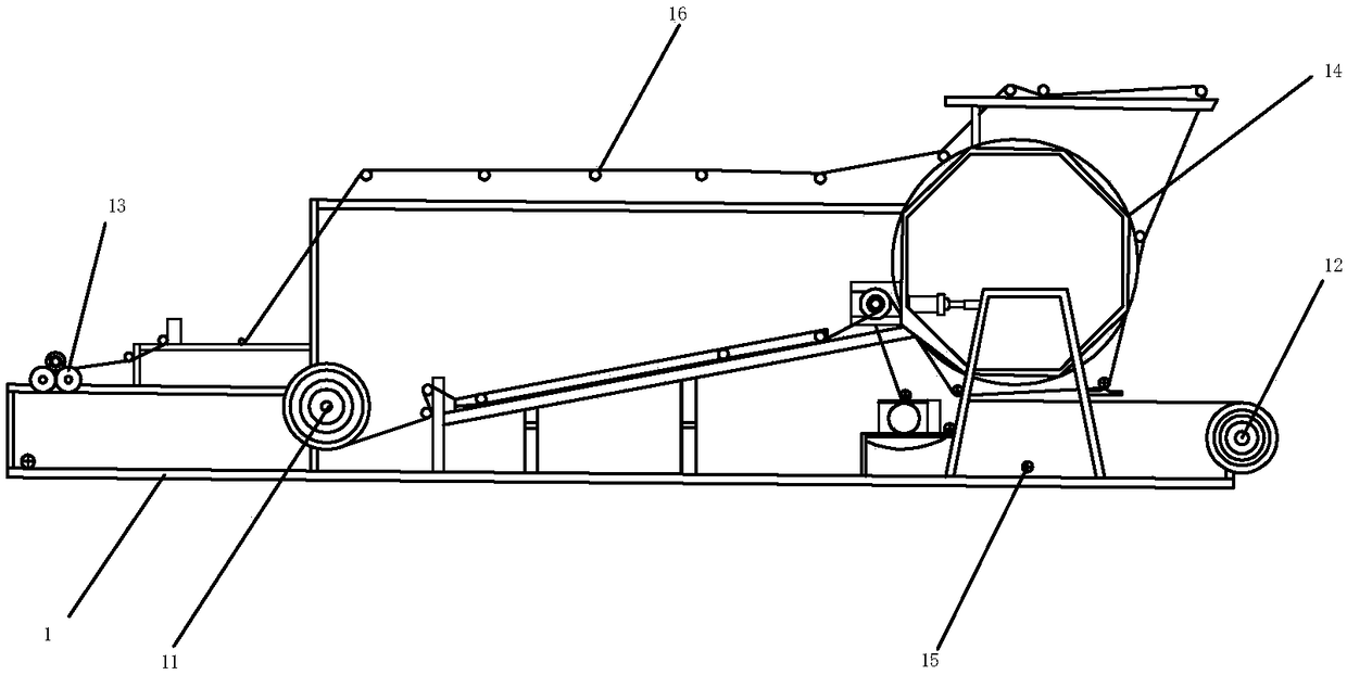
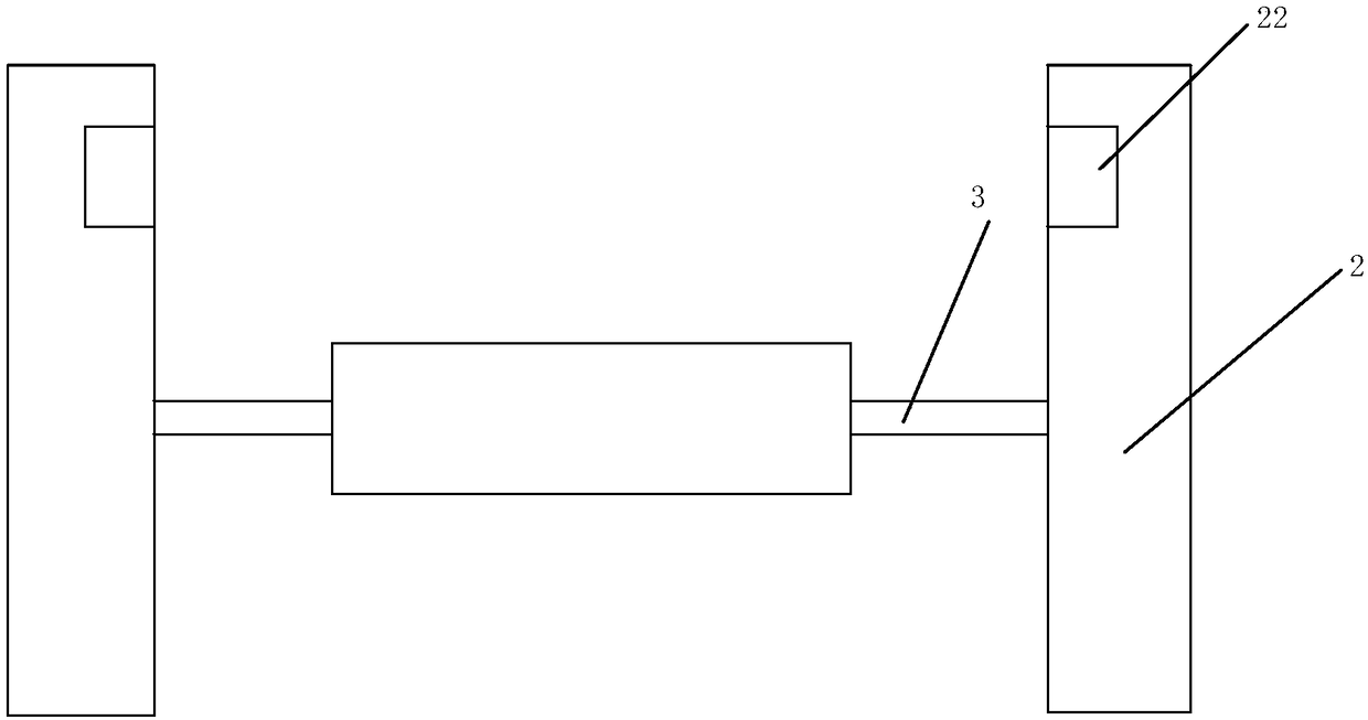
[0029] Embodiment 1: a kind of vertical mesh belt composite machine, such as figure 1 As shown, it includes a frame 1 and a bottom material frame 11 arranged on the frame 1, an upper material frame 12, a finished material frame 13, a drying cylinder 14, a power transmission mechanism 15, and a traction mechanism 16 composed of a plurality of pressing rollers. , wherein the upper material rack 12 and the bottom material rack 11 both include a fixed material rack 2 fixedly connected to both ends of the frame 1 and a detachable material rack 3 for cloth suiting, each fixed material rack 2 is provided with a storage tank 21 , and a gap 22 communicating with the storage tank 21 is provided in the fixed material rack 2 , and the detachable material rack 3 can be placed in the storage tank 21 through the gap 22 and between the two fixed material racks 2 .

[0030] The power transmission mechanism 15 of the vertical mesh belt compound machine is mainly driven by the speed regulating m...

Embodiment 2

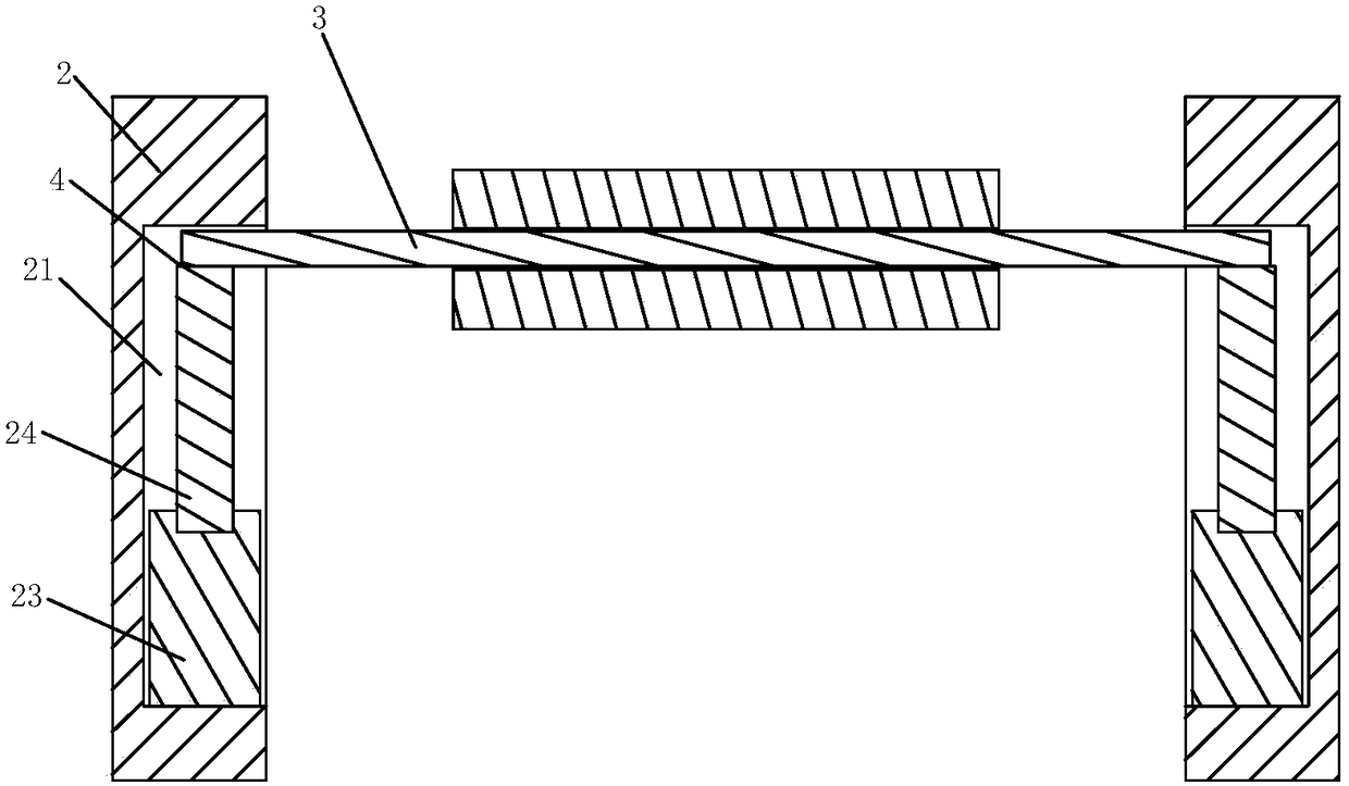
[0033]Embodiment 2: a kind of vertical mesh belt compound machine, the difference with embodiment 1 is, as Figure 4 and 5 As shown, when the detachable material rack 3 is mounted on the two telescopic rods 24, the drive cylinder 23 drives the telescopic rod 24 to descend, in order to avoid the detachable material rack 3 from colliding with the fixed material rack 2 during the descent process. Friction occurs on the inner wall, so the diameter of the detachable material rack 3 is slightly smaller than the diameter of the telescopic rod 24; since the diameter of the detachable material rack 3 is slightly smaller than the diameter of the telescopic rod 24, it can be detached when the vertical mesh belt compound machine is working. The material rack 3 may shake on the two telescopic rods 24. In order to make the installation of the detachable material rack 3 between the fixed material racks 2 more stable, a positioning groove 26 is provided on the upper surface of the telescopic ...


PUM


Abstract

The invention discloses a feeding device of a vertical net belt combination machine. The feeding device comprises a rack, a bottom material rest, a top material rest, a finished product material rest,a drying drum, a power transmission mechanism and a traction mechanism, wherein the bottom material rest, the top material rest, the finished product material rest, the drying drum, the power transmission mechanism and the traction mechanism are arranged on the rack; the top material rest and the bottom material rest each comprise detachable material rests for winding cloth and fixed material rests fixedly arranged at the two ends of the rack; the detachable material rests are arranged between the two fixed material rests; the fixed material rests are both provided with notches for embedmentof the detachable material rests; storage grooves communicating with the corresponding notches are formed in the positions, located below the notches, of the fixed material rests; driving cylinders are arranged in the storage grooves; telescopic rods of the driving cylinders completely stretch out, the telescopic rods are flush with the lower ports of the notches. According to the feeding device,the detachable material rests are arranged on the fixed material rests with less effort, and the working efficiency is improved.

Description

technical field [0001] The invention relates to a composite machine, in particular to a feeding device used in a vertical mesh belt composite machine. Background technique [0002] The general composite machine refers to a kind of composite equipment in home textile, clothing, furniture, automobile interior decoration and other related industries. , suitable for shoemaking, clothing, decoration, automobile and other industries, has the characteristics of flatness without wrinkle and firm fit; due to the use of high temperature resistance, it is more firm and smooth. At the same time, the feeding pressure roller is moved by the air cylinder, which can feed the material quickly, conveniently and accurately. [0003] For example, a needle-edge type mesh belt compound machine (application number 201110439798.6) disclosed on the patent application website includes a frame, a bottom material rack, an upper layer material rack, a finished material rack, a drying cylinder, and a me...

Claims


Application Information

Patent Timeline
IPC IPC(8): B65H16/06B65H39/16
CPCB65H16/06B65H39/16B65H2701/1842
Inventor 郭宏兵还春生徐炜
Owner JIANGSU YUANHUA LIGHT CHEM EQUIP
Learn More