
Laboratory test device and method for dynamic electric voltage recovery device

A technology of dynamic voltage recovery and testing equipment, which is applied in the direction of measuring equipment, instruments, measuring electricity, etc., can solve the problems of very high test conditions and high test costs, simplify test lines and loads, save power consumption, and reduce research and development costs Effect

Active Publication Date: 2011-06-01
CHINA ELECTRIC POWER RES INST +3
View PDF0 Cites 0 Cited by
  • Summary
  • Abstract
  • Description
  • Claims
  • Application Information

AI Technical Summary

Problems solved by technology

The development of high-voltage and large-capacity DVR requires very high test conditions. Taking the 2MVA with a small capacity as an example, to simulate on-site working conditions, a high-voltage three-phase large-capacity AC power supply, a large-capacity three-phase AC load, and supporting high-voltage Low-voltage switches and various protective equipment, the test cost is very high

Method used


Image

  • Laboratory test device and method for dynamic electric voltage recovery device
  • Laboratory test device and method for dynamic electric voltage recovery device
  • Laboratory test device and method for dynamic electric voltage recovery device

Examples


Embodiment Construction

[0021] The present invention will be described in detail below in conjunction with the accompanying drawings and embodiments.

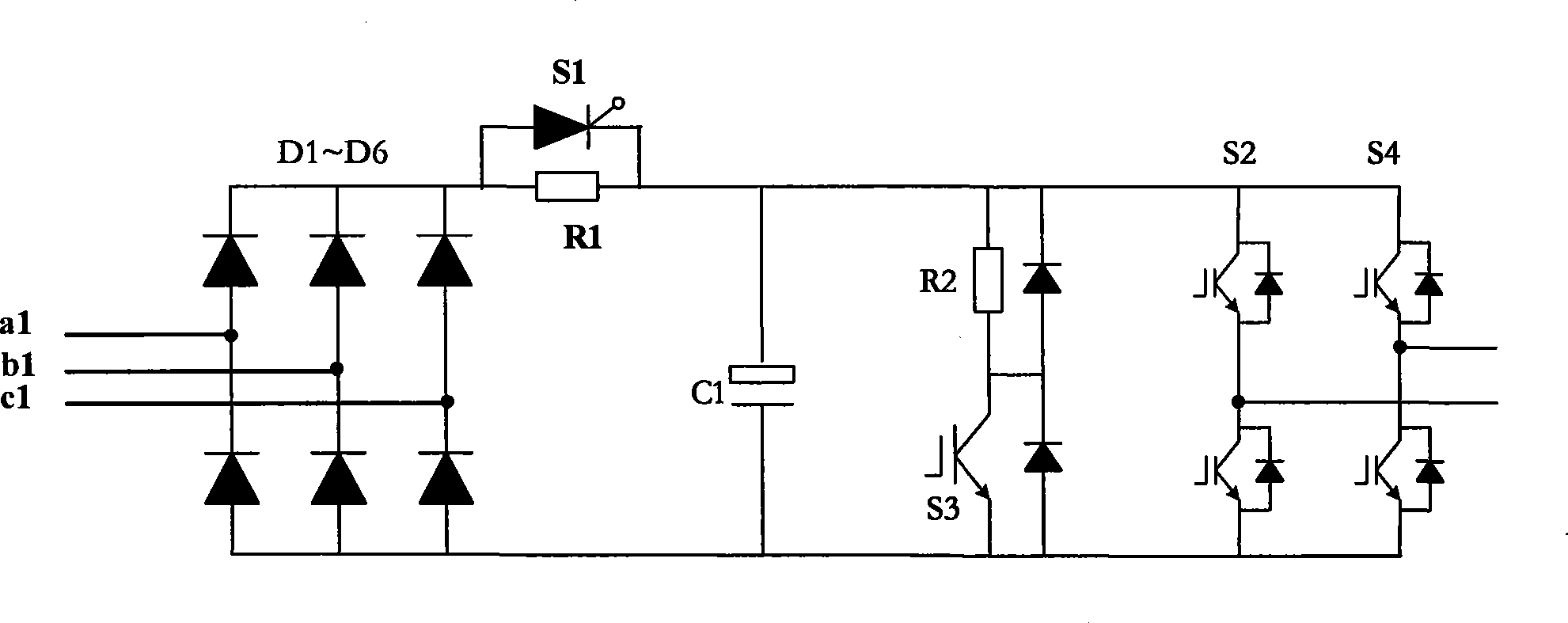
[0022] The topology of the power unit of the DVR device mainly includes three-phase half-bridge and three-phase full-bridge. The three-phase half-bridge topology is suitable for the three-phase power grid balance system; when the three-phase power grid is unbalanced, its control performance will deteriorate, and even failure will occur. Considering the large capacity of the high-voltage DVR device and the unbalanced three-phase power supply most of the time , the actual device mostly adopts a three-phase full-bridge structure. The present invention also adopts a three-phase full-bridge structure.

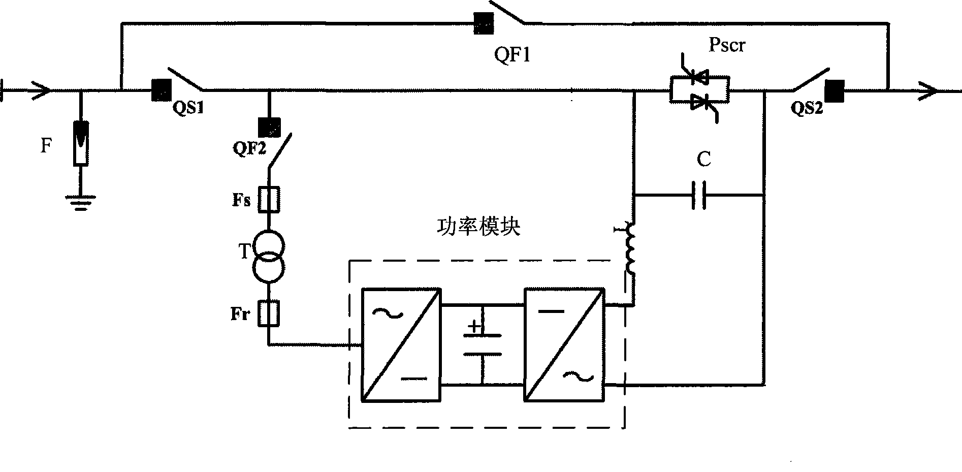
[0023] like figure 1 As shown, the present invention includes a single-wire main circuit suitable for high-voltage and low-voltage DVRs. The input signal of the single-wire main circuit is divided into three parallel signals: the first road is grounded th...


PUM


Abstract

The invention relates to laboratory testing device of a dynamic voltage restorer and a method thereof, wherein, the device comprises a single wire system main circuit, and an input signal of circuit is divided into three parallel signals: the first signal is grounded by a lighting arrester; the second signal is connected to the output end of the circuit by a by-pass switch; the third signal is connected with an isolation switch in series and then divided into two branches that are connected with output signals in parallel, wherein, one output signal is directly connected with the input end ofa thyristor, and the other output signal is connected with a fuse plug in series after being connected with a DVR switched switch; the fuse plug is connected with another fuse plug in series by beingconnected with a transformer in series, the output end of the fuse plug is connected with a power module in series, and the output end of the power module is connected with a filtering circuit which is connected with the thyristor in series; two output signals in the third signal are connected with each other in parallel and are then output after being connected with another isolation switch in series, and the output end of the third signal and the output end of the by-pass switch in the second signal are connected with each other in parallel at the output end of the circuit. The invention can be widely applied in various automation devices.

Description

technical field [0001] The invention relates to a test device and method, in particular to a dynamic voltage restorer (DVR) laboratory test device and method. Background technique [0002] With the development of science and technology, computers, frequency converters and various precision automation equipment have been widely used. While improving production efficiency, they also put forward higher requirements for the power quality of the power supply. Relevant surveys show that complaints about power quality due to voltage sags account for a large proportion of power distribution systems, especially in high-tech parks, large hospitals, military industrial units, and important government departments. DVR is a static series power quality adjustment device, which is mainly used to ensure the voltage stability of the user side when power quality problems such as power supply voltage drop, flicker, and interruption occur. By detecting the voltage on the power supply side and...

Claims


Application Information

Patent Timeline
Patent Type & Authority Patents(China)
IPC IPC(8): G01R31/00
Inventor 乔尔敏邓占锋赵波韩天绪蒋晓春赵小英张柯
Owner CHINA ELECTRIC POWER RES INST
Learn More