
Fiber drawing furnace for optical fiber manufacturing

A wire drawing furnace and optical fiber preform technology, which is applied in the field of optical fiber manufacturing, can solve problems such as air flow instability, achieve the effects of reducing consumption, solving air flow instability, and reducing production costs

Inactive Publication Date: 2018-08-28
芜湖致新信息科技有限公司
View PDF2 Cites 0 Cited by
  • Summary
  • Abstract
  • Description
  • Claims
  • Application Information

AI Technical Summary

Problems solved by technology

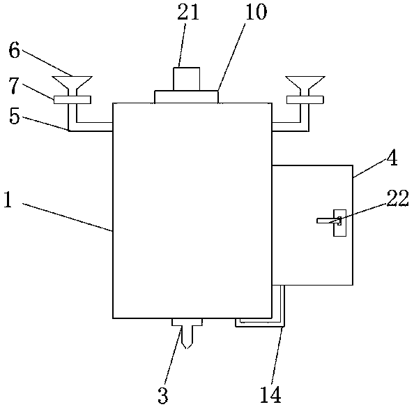
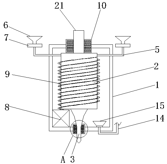
[0005] Aiming at the deficiencies of the prior art, the present invention provides a drawing furnace for optical fiber manufacturing, which solves the problem of unstable air flow in the existing optical fiber drawing furnace

Method used


Image

  • Fiber drawing furnace for optical fiber manufacturing
  • Fiber drawing furnace for optical fiber manufacturing
  • Fiber drawing furnace for optical fiber manufacturing

Examples


Embodiment Construction

[0023] The following will clearly and completely describe the technical solutions in the embodiments of the present invention with reference to the accompanying drawings in the embodiments of the present invention. Obviously, the described embodiments are only some, not all, embodiments of the present invention. Based on the embodiments of the present invention, all other embodiments obtained by persons of ordinary skill in the art without making creative efforts belong to the protection scope of the present invention.

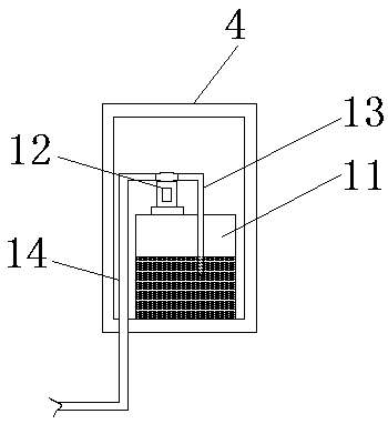
[0024] An embodiment of the present invention provides a drawing furnace for optical fiber manufacturing, such as Figure 1-5 As shown, the shell 1 and the optical fiber preform 21 are included, the inside of the shell 1 is fixedly installed with a heating furnace 2, the bottom of the inner wall of the shell 1 is fixedly installed with a heating box 8, and the inside of the heating box 8 is provided with a heating wire 9, and the heating wire 9 is far away from...


PUM


Abstract

The invention provides a fiber drawing furnace for optical fiber manufacturing, and relates to the field of optical fiber manufacturing. The fiber drawing furnace for optical fiber manufacturing comprises a shell and an optical fiber perform, wherein a heating furnace is fixed in the shell; a heating box is fixed at the bottom of the inner wall of the shell; a heating fiber is arranged in the heating box; the bottom of the heating furnace is communicated with a discharge pipe; one end, away from the heating furnace, of the discharge pipe penetrates through the shell and extends to the exteriorof the shell. According to the fiber drawing furnace for optical fiber manufacturing, two gas inlets are provided, one for introducing argon and one for introducing helium; a control valve controls the flow to strike a balance between the argon and the helium and form a stable gas flow; the argon can effectively seal the helium in a furnace body, thus the helium consumption is greatly reduced, and the production cost of optical fiber drawing is lowered; a fan sucks gas from a gas collection hood so that the gas in the heating furnace always flows downward to form a stable gas flow; meanwhile,residues generated in a fiber drawing process also can be sucked out.

Description

technical field [0001] The invention relates to the technical field of optical fiber manufacturing, in particular to a drawing furnace for optical fiber manufacturing. Background technique [0002] Optical fiber is the abbreviation of optical fiber. It is a fiber made of glass or plastic. It can be used as a light transmission tool. The transmission principle is "total reflection of light". It is widely used because of its advantages of high precision and reliable working performance. [0003] Optical fibers are obtained by so-called "drawing", during which the bottom of the optical fiber preform is softened by heating, usually the drawing system used for this process has a drawing furnace for heating the optical fiber preform, cooling the drawn The cooling device for the glass optical fiber, the coating device for coating resin around the drawn glass optical fiber, and the coiling device for coiling the coated optical fiber. The airflow of the existing optical fiber drawin...

Claims


Application Information

Patent Timeline
IPC IPC(8): C03B37/029
CPCC03B37/029
Inventor 周佩龙
Owner 芜湖致新信息科技有限公司
Learn More