Fuel oil jetting system of heavy oil engine and aircraft engine

A fuel injection system and fuel injection technology, applied in the direction of engine components, machines/engines, fuel injection devices, etc., can solve the problems of substandard emissions, high viscosity of heavy oil, difficulty in starting the engine, etc., to achieve full combustion, full combustion and The effect of using

Pending Publication Date: 2018-08-28
CHONGQING LONCIN ENGINE +1
View PDF0 Cites 0 Cited by
  • Summary
  • Abstract
  • Description
  • Claims
  • Application Information

AI Technical Summary

Problems solved by technology

[0002] As the fuel for the engine, heavy oil will become the power trend of small and medium-sized UAVs; however, heavy oil has high viscosity and poor low-temperature fluidity, resulting in a worse atomization effect than ordinary light oil, affecting the combustion effect, and even making it difficult to start the engine and Emissions are not up to standard
[0003] In the prior art, in order to ensure that the heavy fuel oil engine can have good atomization and start-up, there are fuel supply methods such as carburetor + auxiliary preheating technology, mechanical injection (fuel direct injection), electronically controlled fuel injection, etc.; however, structurally It is still the original EFI method, which cannot achieve reliable atomization of heavy oil and cannot organize efficient combustion of mixed fuels, which makes the power, economy and emission of heavy oil used in engines unable to achieve the desired effect, thus making heavy oil The application cannot be popularized on a large scale

Method used


Image

  • Fuel oil jetting system of heavy oil engine and aircraft engine
  • Fuel oil jetting system of heavy oil engine and aircraft engine
  • Fuel oil jetting system of heavy oil engine and aircraft engine

Examples


Embodiment Construction

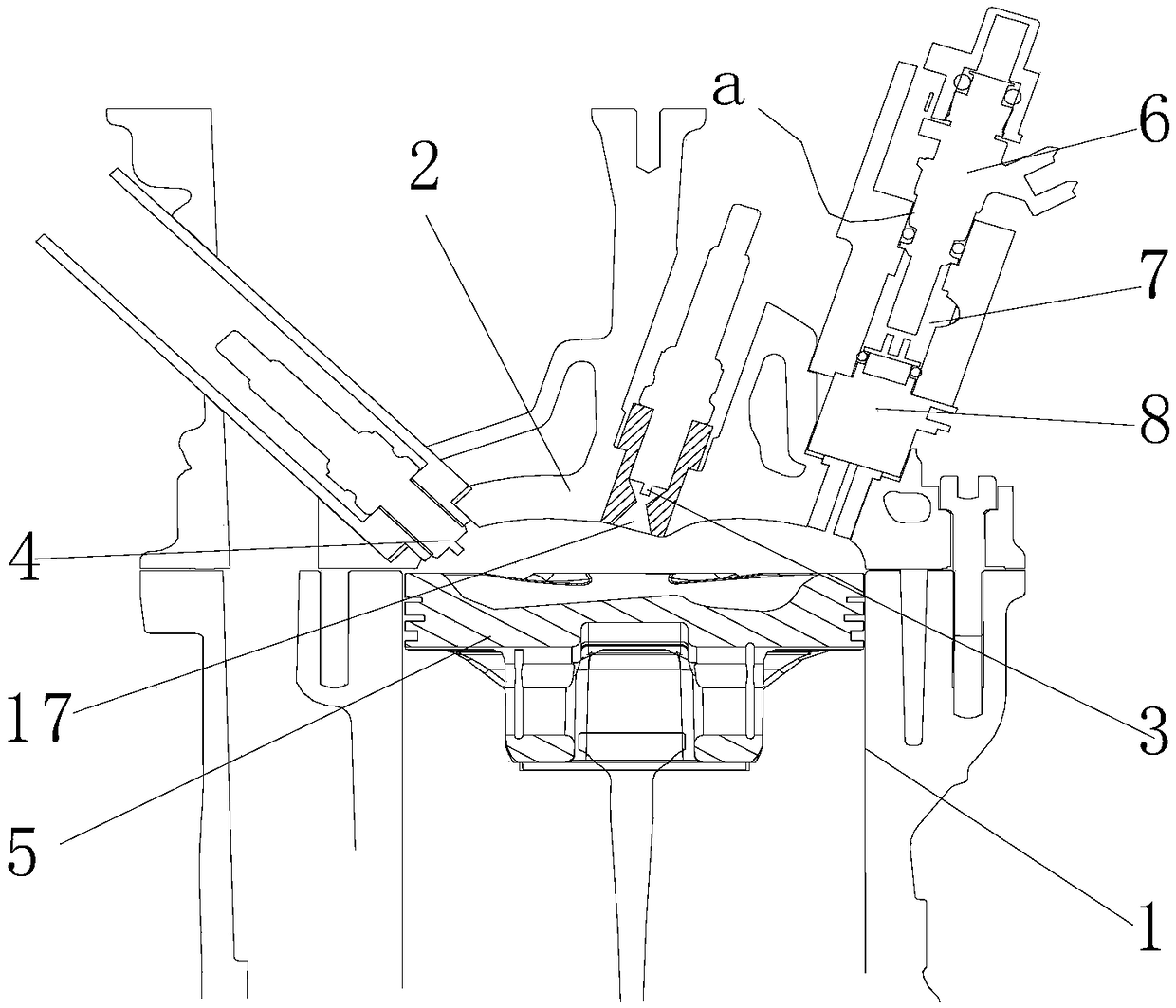
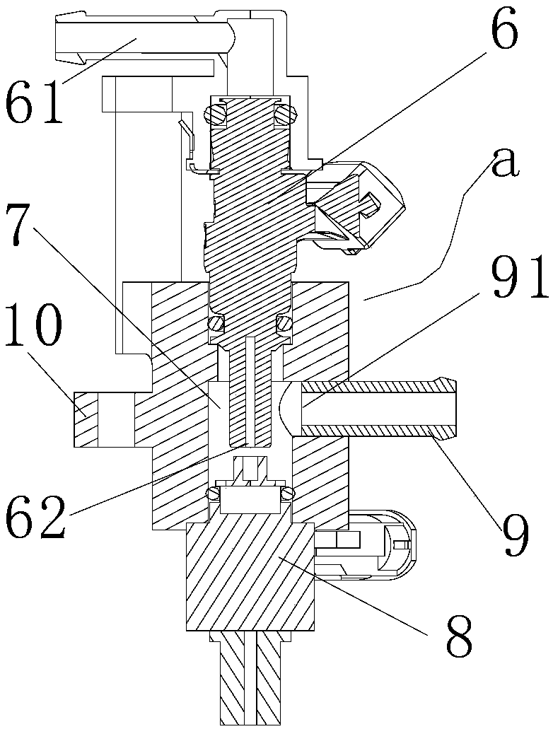
[0018] As shown in the figure: the heavy oil engine fuel injection system of this embodiment includes a compressed air system and a fuel injection assembly, and the compressed air system includes an air compressor and an air supply pipeline; the fuel injection assembly includes a fuel nozzle 6, a premixing chamber 7 and the oil-air mixing nozzle 8, the fuel injection port of the fuel nozzle 6 and the compressed air inlet (that is, the compressed air outlet of the air compression system) are arranged in the premixing chamber 7, and the oil-air mixing nozzle 8 communicates with the premixing chamber 7 The atomized mixed fuel gas formed by fuel and compressed air in the premixing chamber is sent to the combustion chamber of the engine; the auxiliary low-pressure air is used to realize premixing in the premixing chamber and further atomize the fuel sprayed by the fuel nozzle to ensure direct injection in the later stage After entering the combustion chamber, more sufficient atomiza...


PUM


Abstract

The invention discloses a fuel oil jetting system of a heavy oil engine and an aircraft engine. The fuel oil jetting system comprises a compressed air system and a fuel oil jetting system, wherein thecompressed air system comprises an air compressor and an air supplying pipeline; the fuel oil jetting assembly comprises a fuel oil nozzle, a premixing chamber and an oil-gel mixing nozzle; an oil jetting port of the fuel oil nozzle and a compressed air inlet which communicates with the air supplying pipeline are formed in the premixing chamber; the oil-gas mixing nozzle communicates the premixing chamber and is used for feeding atomized mixed oil which is formed through fuel oil and compressed air in the premixing chamber into a combustion chamber of the engine. According to the fuel oil jetting system of the heavy oil engine, a fuel jetting structure assisting air atomizing and premixing is mounted on a cylinder head of the engine, so that heavy oil can be fully atomized, and uniform combustion mixing gas can be obtained by mixing; and moreover, the combustion can be efficiently carried out; the dynamic property, the economic property and the emission property of the heavy oil applied to the engine can be ensured; and the energy conservation, the environmental protection and low cost are achieved after the heavy oil is applied to the engine.

Description

technical field [0001] The invention relates to an engine and its application, in particular to a fuel injection system for a heavy oil engine and an aeroengine. Background technique [0002] As the fuel for the engine, heavy oil will become the power trend of small and medium-sized UAVs; however, heavy oil has high viscosity and poor low-temperature fluidity, resulting in a worse atomization effect than ordinary light oil, affecting the combustion effect, and even making it difficult to start the engine and Emissions are not up to standard. [0003] In the prior art, in order to ensure that the heavy fuel oil engine can have good atomization and start-up, there are fuel supply methods such as carburetor + auxiliary preheating technology, mechanical injection (fuel direct injection), electronically controlled fuel injection, etc.; however, structurally It is still the original EFI method, which cannot achieve reliable atomization of heavy oil and cannot organize efficient c...

Claims


Application Information

Patent Timeline
Patent Type & Authority Applications(China)
IPC IPC(8): F02M63/00
CPCF02M63/00
Inventor 唐程石晓东刘小林翟明明闪颂武罗晏林成
Owner CHONGQING LONCIN ENGINE
Why Eureka
Try Eureka