
Secondary battery top cover and secondary battery thereof

A secondary battery, top cover technology, applied in battery cover/end cover, battery pack components, battery box/jacket, etc., can solve problems such as difficulty, high manufacturing cost, and increased stamping process

Pending Publication Date: 2018-08-28
东莞百思利新能源科技有限公司
View PDF0 Cites 5 Cited by
  • Summary
  • Abstract
  • Description
  • Claims
  • Application Information

AI Technical Summary

Problems solved by technology

At present, the common battery products are to manufacture the explosion-proof valve and the top cover separately, and then weld the explosion-proof valve to the top cover, but this will lead to high manufacturing cost and complicated process
[0004] At present, some researchers have also proposed to stamp the top cover sheet to process the explosion-proof valve integrated with the top cover sheet, so as to save the welding process, but the redundant top cover sheet waste generated by processing the explosion-proof valve needs to be removed during the integrated molding. , which greatly increases the difficulty of the stamping process, and the thickness of the top cover is generally thicker (>2mm), and it is very difficult to form a thinner explosion-proof valve with explosion-proof function by stamping. Therefore, this integrated Roof structure products have not yet been industrialized and are still a technical problem plaguing the industry

Method used


Image

  • Secondary battery top cover and secondary battery thereof
  • Secondary battery top cover and secondary battery thereof
  • Secondary battery top cover and secondary battery thereof

Examples


Embodiment Construction

[0028] The secondary battery top cover and the secondary battery thereof of the present invention will be described below with reference to the accompanying drawings.

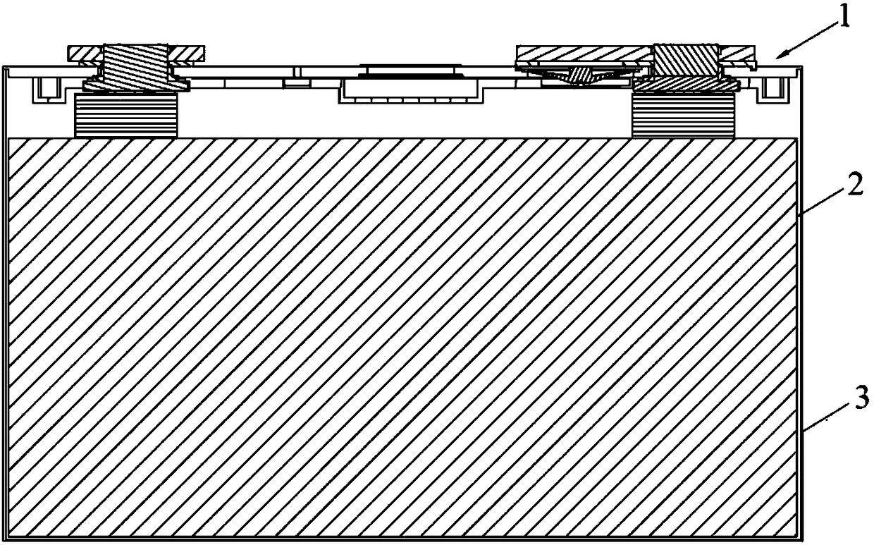
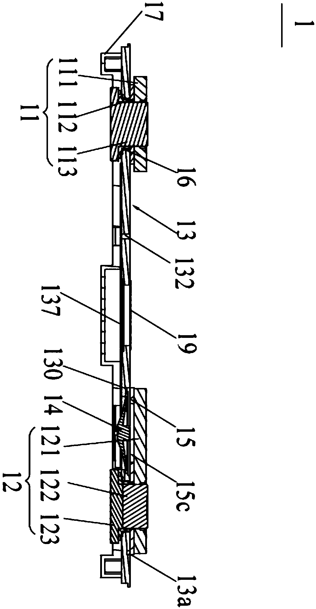
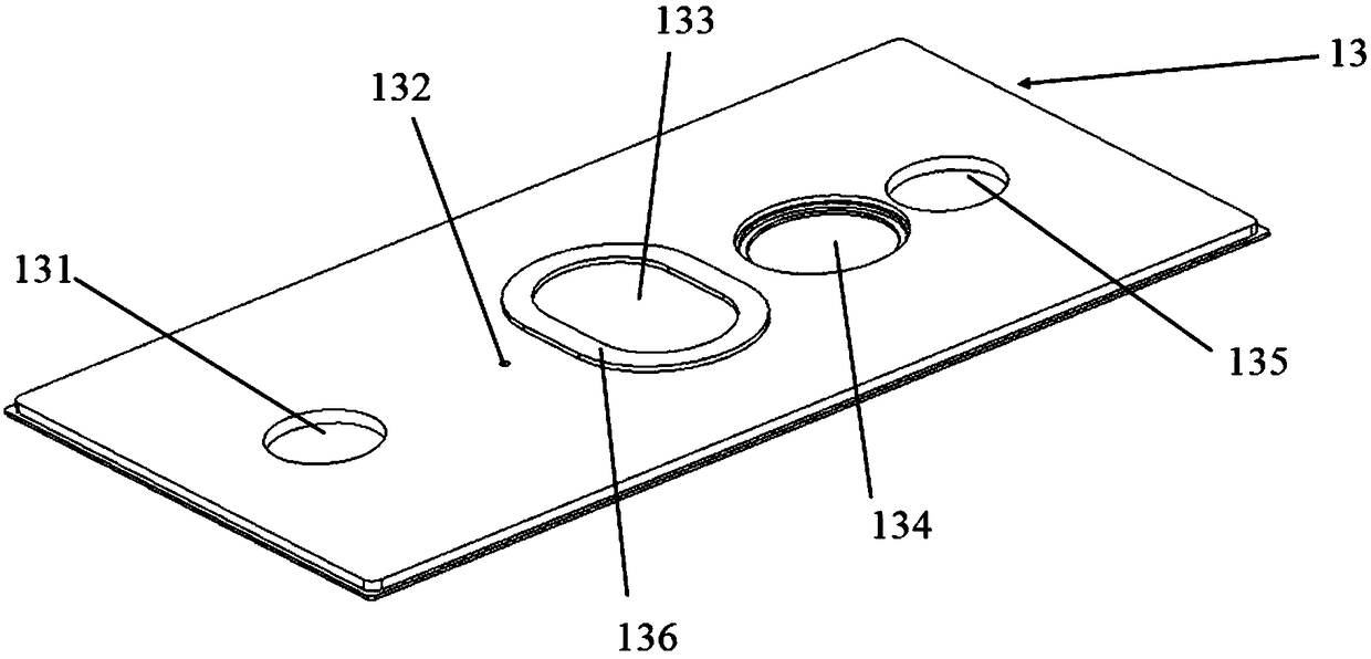
[0029] refer to Figure 1~4 , The secondary battery includes a secondary battery top cover 1, an electric cell 2 and a casing 3 for containing the electric cell, and the secondary battery electrolyte (not shown) soaking the electric cell is filled in the casing. The secondary battery top cover 1 includes a top cover sheet 13 , and a first electrode unit 11 , a second electrode unit 12 , a flip sheet 14 , a liquid injection hole 132 and an explosion-proof valve 137 arranged on the top cover sheet 13 . The top cover sheet 13 is provided with a flip sheet fixing hole 134, a first mounting hole 131, a second mounting hole 135 and an explosion-proof hole 133. The first electrode unit 11 is insulated and sealed in the first mounting hole 131, and the second electrode unit 12 The insulating seal is installed in the s...


PUM

PropertyMeasurementUnit
Lengthaaaaaaaaaa

Abstract

The invention provides a secondary battery top cover which comprises a top cover sheet and an anti-explosion valve, wherein the top cover sheet is provided with an anti-explosion hole; the anti-explosion valve is arranged in the anti-explosion hole; the top cover sheet and the anti-explosion valve are of an integrated structure; the top cover sheet extends around the anti-explosion hole towards adirection away from the anti-explosion valve, so as to form a boss; in the vertical direction, a length ratio of the top cover sheet to the anti-explosion valve ranges from 2.5 to 7; a ratio of the length of the boss in the horizontal direction to the length of the top cover sheet in the vertical direction ranges from 1 to 10. Through the integration of the top cover sheet and the anti-explosion valve, assembling and welding working procedures between the top cover sheet and the anti-explosion valve can be avoided, so that the working procedures are simple, and the airtightness is high; moreover, through the arrangement of the boss, the problem on removal of a redundant top cover sheet material can be solved, and the overall intensity of positions around the anti-explosion hole and even the top cover sheet can be also enhanced. In addition, the applicator of the invention also makes a further design for the sizes of the top cover sheet, the anti-explosion valve and the boss by a creative idea, so that the technical difficulty in integrally forming a relatively thin anti-explosion valve having the anti-explosion function on the top cover sheet can be solved.

Description

technical field [0001] The invention relates to the field of energy storage devices, in particular to a secondary battery top cover and the secondary battery. Background technique [0002] In modern society, more and more driving power sources of electric tools and new energy vehicles are developing in the direction of high capacity and high safety. Batteries are widely used in electric tools and new energy vehicles due to their excellent characteristics such as high capacity . In addition to high capacity, these batteries should also have good safety in order to reach the standard of use and meet people's needs. [0003] In the prior art, when the internal pressure of the battery is too high, in order to prevent the battery from exploding, it is necessary to leak the pressure in the battery shell. The current explosion-proof method is to install an explosion-proof valve on the top cover of the battery. When it is large, the pressure is released through the explosion-proof...

Claims


Application Information

Patent Timeline
IPC IPC(8): H01M2/04H01M2/12H01M50/147H01M50/342
CPCH01M50/147H01M50/3425Y02E60/10
Inventor 邓平华谭婷权伟民马威
Owner 东莞百思利新能源科技有限公司
Learn More