
Fire hose cleaning device

A cleaning device and fire hose technology, applied in fire rescue and other directions, can solve the problems of affecting cleaning, water discharge, poor cleaning effect, etc., to prevent re-contamination and improve cleaning efficiency.

Inactive Publication Date: 2018-08-31
成都尚智恒达科技有限公司
View PDF0 Cites 0 Cited by
  • Summary
  • Abstract
  • Description
  • Claims
  • Application Information

AI Technical Summary

Problems solved by technology

[0003] The fire hose is one of the essential equipment in the fire equipment. The residual stains on the surface of the fire hose after use will corrode the fire hose, so the cleaning of the fire hose is very important, and then the existing fire hose There are still deficiencies in the cleaning device. First, before the hose is cleaned, the residual moisture inside the hose will affect the quality of cleaning. However, the existing cleaning device does not discharge this part of the water, which affects cleaning; secondly, the existing The special cleaning device cannot dry the hose in time after cleaning, so that the water on the hose will cause the hose to be stained again, causing secondary pollution and poor cleaning effect

Method used


Image

  • Fire hose cleaning device
  • Fire hose cleaning device
  • Fire hose cleaning device

Examples


Embodiment Construction

[0021] The following will clearly and completely describe the technical solutions in the embodiments of the present invention with reference to the accompanying drawings in the embodiments of the present invention. Obviously, the described embodiments are only some, not all, embodiments of the present invention.

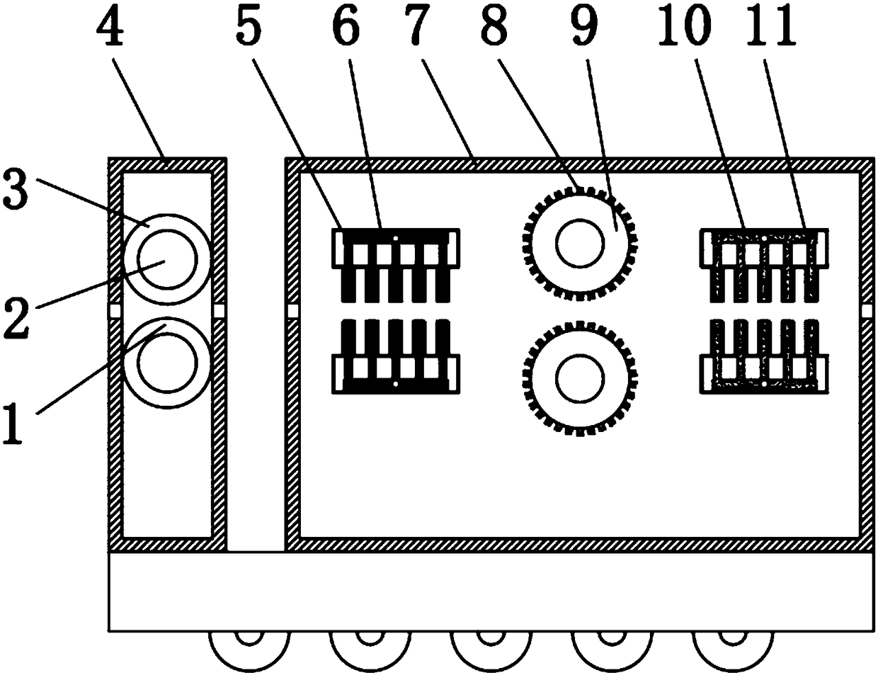
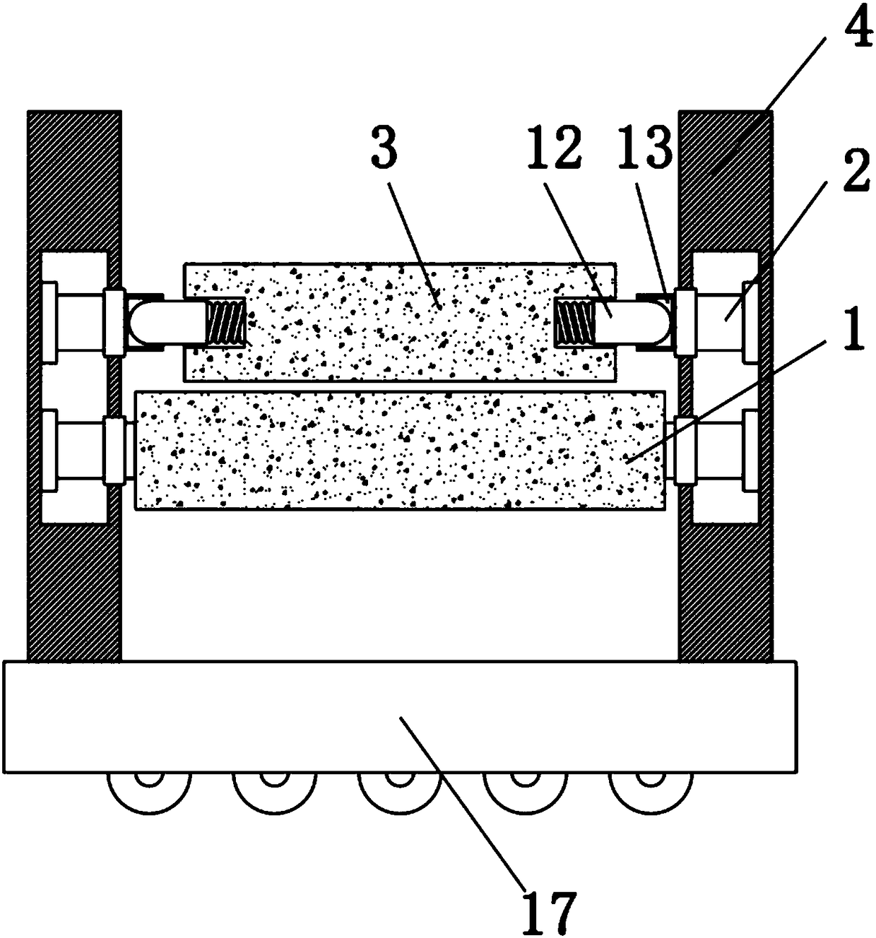
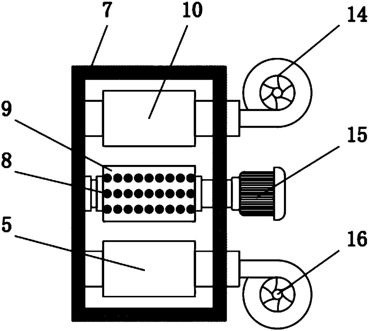
[0022] refer to Figure 1-3 , a fire hose cleaning device, including a second drum 3, a drying box 10 and a base 17, the top end of the base 17 is welded with a drainage box 4, and the inner top and bottom of the drainage box 4 are rotatably connected by a shaft sleeve There is a rotating shaft 2, and the two inner sides close to the top of the base 17 in the rotating shaft 2 are rotatably connected with the first roller 1, and the two inner sides away from the top of the base 17 in the rotating shaft 2 are provided with slots 13, and the two slots 13 are all sleeved with elastic bolts 12, one end of the two elastic bolts 12 is elastically connected with the second r...


PUM


Abstract

The invention discloses a fire hose cleaning device. The device comprises a second roller, a blow-drying box and a base. A water drainage box is welded to one end of the top of the base. The top end and the bottom end of the interior of the water drainage box are rotationally connected with rotary shafts through shaft sleeves correspondingly. The inner sides of two rotary shafts, close to the topof the base, are rotationally connected with a first roller. Slots are formed in the inner sides of the other two rotary shafts, away from the top of the base, correspondingly. Elastic plug pins are connected into the two slots correspondingly in a sleeving mode. One ends of the two elastic plug pins are elastically connected with the second roller through springs correspondingly. A cleaning box is welded to the top of the base. According to the fire hose cleaning device, the water drainage box is arranged at the top of the base and internally provided with the two rollers, the two rollers clamp a hose between the inner sides of the two rollers, when the hose moves, water in the hose is drained out under extrusion of the two rollers, and further cleaning is facilitated.

Description

technical field [0001] The invention relates to the technical field of cleaning equipment, in particular to a fire hose cleaning device. Background technique [0002] Fire-fighting equipment refers to the equipment used for fire extinguishing, fire prevention and fire accidents. Equipment for professional fire fighting. The most common fire-fighting equipment: fire extinguishers, which can be divided into three types according to the pressure type of driving fire extinguishers: 1. A fire extinguisher driven by a compressed air. The fire extinguisher is driven by the pressure of compressed gas or liquefied gas released from the gas cylinder on the fire extinguisher. 2. Stored pressure fire extinguisher. A fire extinguisher in which the extinguishing agent is driven by the pressure of compressed gas or extinguishing vapor in the same container as the extinguisher. 3. Chemical reaction fire extinguisher. The extinguishing agent is a fire extinguisher driven by the gas pres...

Claims


Application Information

Patent Timeline
Patent Type & Authority Applications(China)
IPC IPC(8): A62C33/02
CPCA62C33/02
Inventor 任无史晓莉
Owner 成都尚智恒达科技有限公司
Learn More