Machine tool with dedusting and deoiling device
A technology for machine tools and machine tool bodies, applied in the field of machine tools, can solve problems such as difficult removal, troublesome operation, troublesome cleaning work, etc., and achieve the effects of convenient cleaning work, expanding work scope, and improving cleaning efficiency.
- Summary
- Abstract
- Description
- Claims
- Application Information
AI Technical Summary
Problems solved by technology
Method used
Image

Examples
Embodiment 1
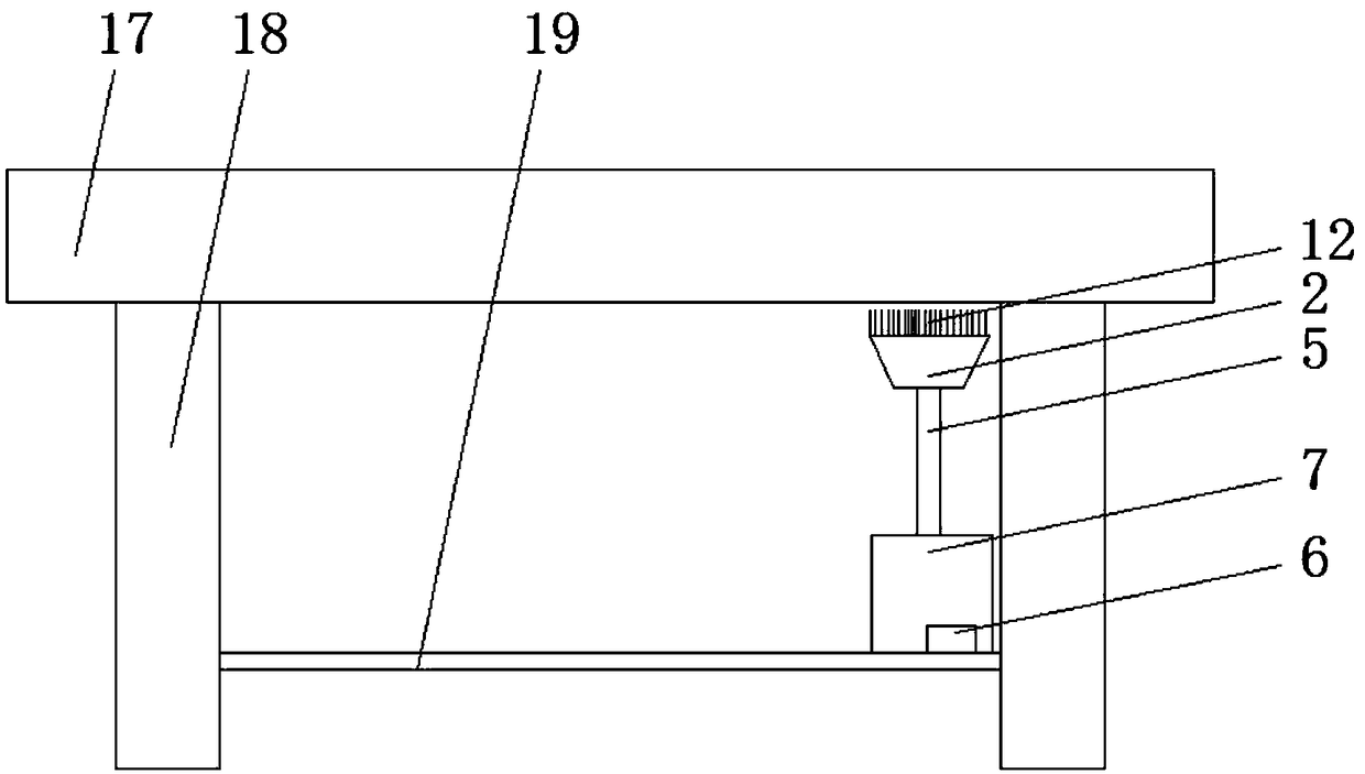
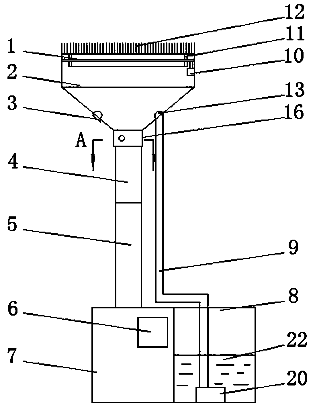
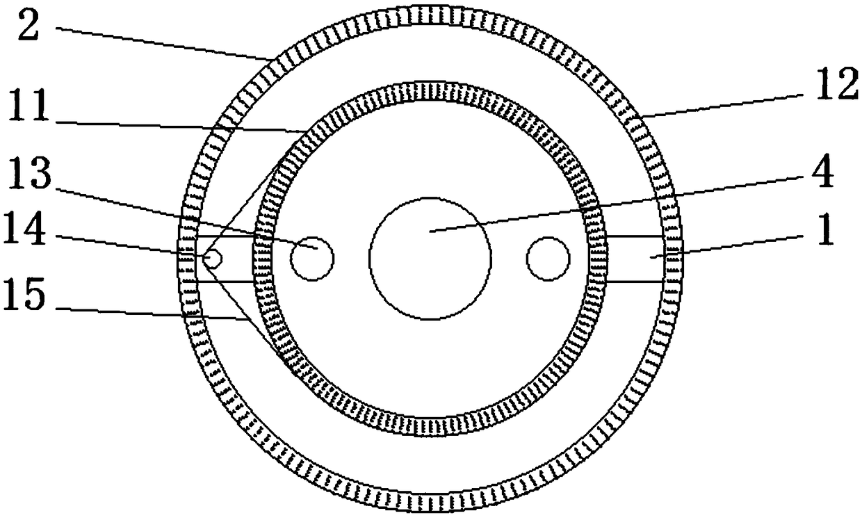
[0030] Embodiment 1, a kind of machine tool with dedusting and degreasing device, comprises machine tool main body 17, dust collection box 7, degassing box 8 and dust collection cover 2, and the bottom of described machine tool main body 17 is provided with symmetrically distributed fixed frame 18, so A slide rail 19 is provided between the fixed brackets 18, and the slide rail 19 is provided with a dust collection box 7 and an oil removal tank 8 that are movably connected, and the upper end of the dust collection box 7 is connected with the dust collection cover 2 through a suction pipe 5 , the inside of the dust collection hood 2 is provided with a fixed rod 1, and the middle part of the fixed rod 1 is provided with a movable connection cleaning ring 11, and the cleaning ring 11 and the bottom of the dust collection hood 2 are provided with a number of evenly distributed cleaning brush wires 12. The upper end of the dust collection hood 2 is provided with a number of uniform ...
Embodiment 2
[0033] Embodiment 2, a machine tool with a dust removal and oil removal device, comprising a machine tool main body 17, a dust collection box 7, an oil removal tank 8 and a dust collection cover 2, the bottom of the machine tool main body 17 is provided with symmetrically distributed fixing frames 18, so A slide rail 19 is provided between the fixed brackets 18, and the slide rail 19 is provided with a dust collection box 7 and an oil removal tank 8 that are movably connected, and the upper end of the dust collection box 7 is connected with the dust collection cover 2 through a suction pipe 5 , the inside of the dust collection hood 2 is provided with a fixed rod 1, and the middle part of the fixed rod 1 is provided with a movable connection cleaning ring 11, and the cleaning ring 11 and the bottom of the dust collection hood 2 are provided with a number of evenly distributed cleaning brush wires 12. The upper end of the dust collection hood 2 is provided with a number of unifo...
PUM
 Abstract
Description
Claims
Application Information
 - R&D
- Intellectual Property
- Life Sciences
- Materials
- Tech Scout
- Unparalleled Data Quality
- Higher Quality Content
- 60% Fewer Hallucinations
Browse by: Latest US Patents, China's latest patents, Technical Efficacy Thesaurus, Application Domain, Technology Topic, Popular Technical Reports.
© 2025 PatSnap. All rights reserved.Legal|Privacy policy|Modern Slavery Act Transparency Statement|Sitemap|About US| Contact US: help@patsnap.com