Nut removal equipment

A nut and equipment technology, applied in the field of prefabricated component production equipment, can solve the problems that different pipe piles cannot be used in common, inaccurate positioning of nut sleeves and nuts, complicated processing and installation, etc.

Pending Publication Date: 2018-08-31
周兆弟
View PDF1 Cites 0 Cited by
  • Summary
  • Abstract
  • Description
  • Claims
  • Application Information

AI Technical Summary

Problems solved by technology

[0006] The defect of this small nut machine is: 1. The nut removal assembly corresponds to the nut one by one, that is, each nut corresponds to a nut removal assembly, and it is necessary to constantly adjust the removal assembly or increase the removal assembly to realize the removal assembly One-to-one correspondence between parts and nuts on the end plate, that is, multiple demoulding components are required to dismantle multiple nuts on the end plate. The small nut machine has poor versatility and poor practicability; in addition, planetary type structure, a driving mechanism drives all the demolition components to rotate, and removes the nuts at the same time, the driving force is insufficient, the overall parts are many, the processing and installation are complicated, and different pipe piles cannot be used universally; 2. The nut sleeve is fixedly connected with the spline gear shaft. When the nut machine is working, if the nut sleeve and the nut are not completely aligned (that is, the axis line of the nut sleeve and the nut axis line are not completely coincident), it will cause interference between the nut sleeve and the nut, resulting in damage to the components; 3 , No matter which way to remove the small nut, the key is to align the center of rotation of the demoulding assembly with the center of the end plate, and in the prior art, the center of rotation of the demoulding assembly and the center of the end plate The position is usually fixed, but the cente

Method used


Image

  • Nut removal equipment
  • Nut removal equipment
  • Nut removal equipment

Examples


Embodiment 1

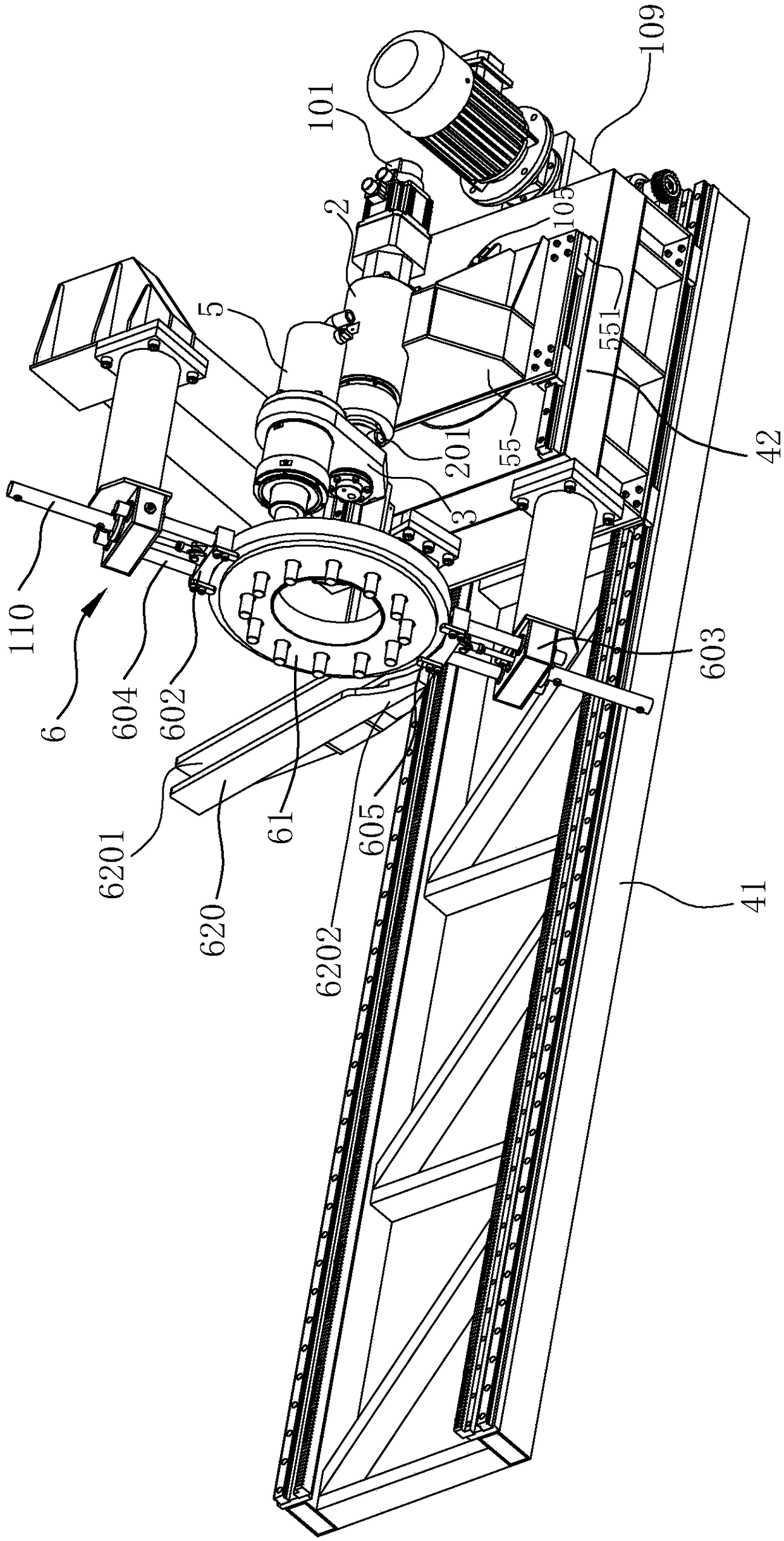
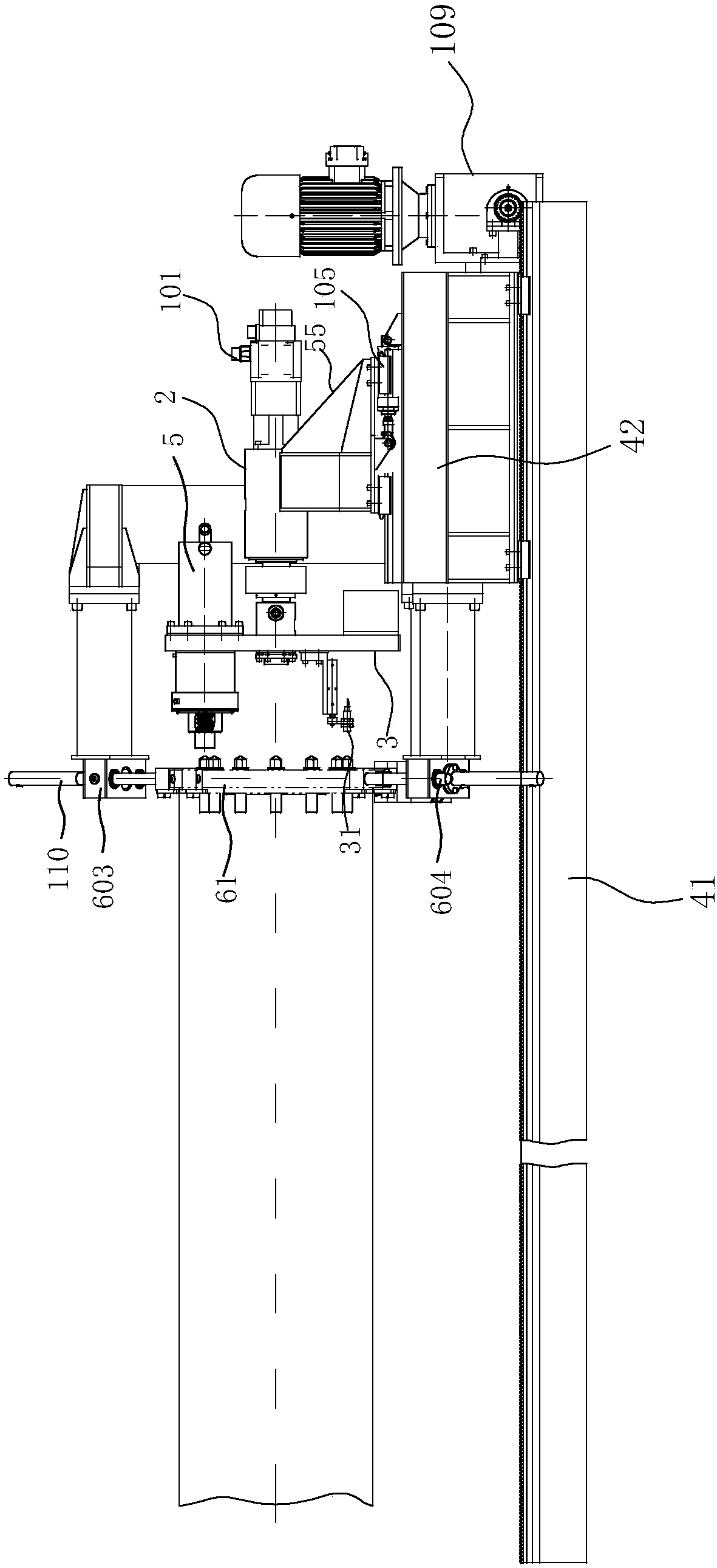
[0088] like Figure 1-8 As shown, the nut removal equipment in this preferred embodiment includes a machine table 41, a first frame 42, a nut removal assembly 5, a first driving mechanism 101 that drives the nut removal assembly 5 to rotate in the circumferential direction of the end plate 61, and is used for clamping. The clamp 6 holding the end plate 61, the delivery device that can remove the end plate 61.

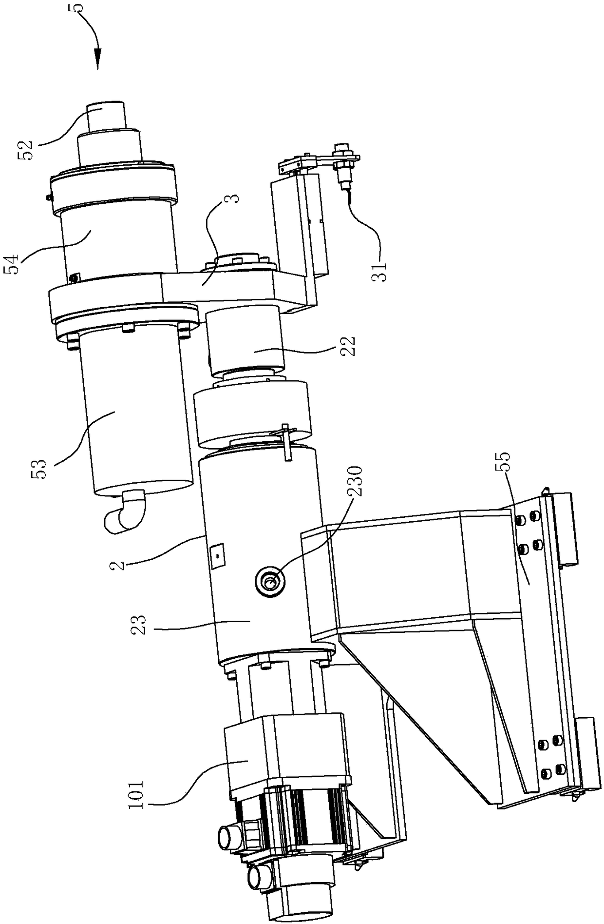
[0089] In this embodiment, the first driving mechanism 101 is a motor, the power output end of the motor is connected to the connecting body 2, and the connecting body 2 is fixedly connected to the nut removal assembly 5 through the connecting piece 3, and the connecting piece 3 is provided with a sensor for sensing the nut. The sensing mechanism 31 is electrically connected to the controller, and the controller controls the action of the first driving mechanism 101 and the second driving mechanism 53 of the nut removal assembly 5 . The nut removal assembly 5 and the i...

Embodiment 2

[0110] like Figures 9 to 17 As shown, the difference between embodiment 2 and embodiment 1 is:

[0111] (1) Embodiment 2 is not provided with conveying device;

[0112] (2) The present embodiment is provided with a positioning mechanism, which enables the rotation center of the nut removal assembly 5 to rotate circumferentially around the central axis of the end plate 61 to quickly and accurately align with the center of the end plate 61:

[0113] like Figures 9 to 13 As shown, the positioning mechanism includes a frame body and an induction assembly 46, and the frame body includes a second frame 43 and a third frame 44, and the nut removal assembly 5 can be mounted on the first frame 42, the second frame 43, the third frame Driven by the frame 44, it moves back and forth, left and right, and up and down, so as to locate quickly and accurately in the three-dimensional direction of space.

[0114] The third frame 44 is located above the second frame 43 and can move with th...

Embodiment 3

[0136] like Figures 18-23 As shown, the difference between embodiment 3 and embodiment 2 is:

[0137] (1) The structure of fixture 6 is different:

[0138] like Figure 18 , 19 As shown, the fourth frame 47 is provided with two opposite jaws 602, and each jaw 602 is correspondingly driven by a sixteenth drive mechanism 116 installed on the fourth frame 47, and the jaws 602 are The sixteenth driving mechanism 116 moves toward the end plate 61 to clamp the end plate 61 , or moves in the opposite direction (a direction away from the end plate 61 ) to release the end plate 61 . Each jaw 602 is correspondingly connected with a second guide rod 614 slidably installed on the fourth frame 47 , and the moving track of the jaw 602 is guided by the second guide rod 614 .

[0139] (2) The induction mechanism 31 is connected with the connector 3 through the cylinder 306:

[0140] like Figure 20-22 As shown, a cylinder 306 is provided at the bottom of the connecting member 3 , the s...


PUM


Abstract

The invention relates to nut removal equipment which comprises a machine, a first rack and a nut removal component, wherein the nut removal component is used for removing nuts on an end plate; the fist rack is movably arranged on the machine and can move back and force along the machine; and the nut removal component is arranged on the first rack and can move along with the first rack. The nut removal equipment is characterized by also comprising a clamp, an induction mechanism, and a first driving mechanism; the clamp is used for clamping the end plate, and the induction mechanism is used forinducting the nuts; the nut removal component and the induction mechanism are driven by the first driving mechanism to synchronously rotate circumferentially around the center shaft of the end plate,therefore when the induction mechanism inducts one nut on the end plate, the nut removal component can aim at one nut on the end plate and can remove the aimed nuts on the end plate in order. Only bythe matching of one nut removal component and the induction mechanism, the nut removal equipment can remove the nuts of the end plate.

Description

technical field [0001] The invention belongs to the field of prefabricated component production equipment in construction technology, and in particular relates to a nut removal device, which is used for removing nuts on end plates of pipe piles. Background technique [0002] The pipe mold is a mold for making pipe piles. In the process of making pipe piles, one end of the pipe mold will be provided with an end plate fixed at the end of the pipe pile. The end plate is connected with the main reinforcement of the steel cage in the pipe pile through several nuts. To connect, usually, the nuts are evenly arranged along the circumference of the end plate. [0003] During the demoulding process, the nuts on the end plate need to be removed. The existing small nut removal method requires technicians to remove the small nuts on the end plate one by one with a hand-held nut remover, which has low automation and low efficiency. [0004] In view of the above problems, the invention pa...

Claims


Application Information

Patent Timeline
IPC IPC(8): B28B21/90B28B13/06
CPCB28B13/065B28B21/90
Inventor 周兆弟
Owner 周兆弟
Why Eureka
Try Eureka