Rotating power output built-in hydraulic rock drilling machine

A hydraulic rock drill and rotary power technology, which is applied in the field of hydraulic rock drills, can solve problems such as unfavorable on-site installation and maintenance, damage to the output shaft of the cantilever, and many falling rocks, so as to facilitate the installation and maintenance of the rock drill, slow down the axial movement force, and save space volume effect

Active Publication Date: 2018-08-31
HEBEI HONGYUAN HYDRAULIC MACHINERY
View PDF5 Cites 2 Cited by
  • Summary
  • Abstract
  • Description
  • Claims
  • Application Information

AI Technical Summary

Problems solved by technology

[0003] Because the rock drilling machine on the mining site is located directly under the mining operation point, there are many rockfalls; the water for rock drilling operation will be directly splashed on the rock drilling machine, which is very prone to corrosion, and the production and operation conditions on site are very bad
[0004] The external hydraulic motor plus transmission mechanism has the following disadvantages at the job site: ①The rotating power output part of this external hydraulic motor plus transmission mechanism is suspended outside the box due to the bolt connection, and because the motor output shaft cantilever is too long, it is easy to be damaged. Due to the influence of high-frequency vibration of the hydraulic rock drill, the transmission is unstable, which makes the output shaft of the cantilever prone to damage
②The external hydraulic motor needs to add an additional set of gear output device to realize the transmission. Adding bearings and gear transmission structural components will make the output of rotational kinetic energy unstable, resulting in shortened service life of bearings and output shafts, resulting in reduced transmission efficiency
③The external hydraulic motor is connected and fixed on the rotating box by 4 bolts, which is easily affected by the high-frequency vibration of the hydraulic rock drill, and the bolts are loose and may fall off
Moreover, long-term water splashing on the bolts in rock drilling operations will easily cause the bolts to corrode and break
④ The external hydraulic pipeline connected to the external hydraulic motor is easily scratched and damaged by ore during operation, which affects the operation
⑤The external hydraulic motor and transmission mechanism increase the volume and weight of the rock drill, which is not conducive to on-site installation and maintenance
The above points bring greater loss to the user unit and reduce production efficiency

Method used


Image

  • Rotating power output built-in hydraulic rock drilling machine
  • Rotating power output built-in hydraulic rock drilling machine
  • Rotating power output built-in hydraulic rock drilling machine

Examples


Embodiment Construction

[0045] In order to deepen the understanding of the present invention, the present invention will be further described below in conjunction with the accompanying drawings.

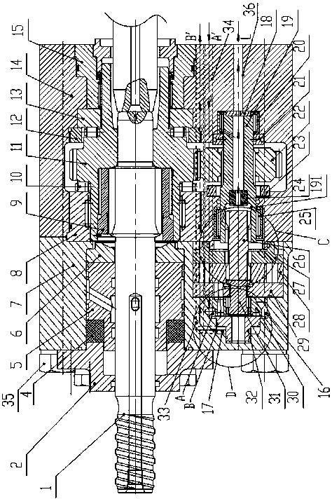
[0046] Such as Figure 1-7 As shown, a hydraulic rock drill with a built-in rotary power output of the present invention includes a box cover 7, a box body 14 connected to the box cover 7, a transmission part, and a power output part;

[0047] The transmission part includes the shank 1 passing through the box body 14 and the box cover 7, the gland 2 fixed on the left end surface of the box cover 7, the water jacket 5 installed in the box cover 7, the guide sleeve 9, and the A hollow gear shaft 11, the gear shaft 11 is coaxially arranged on the peripheral surface of the shank 1;

[0048] The right side of the gear shaft 11 is provided with a rear bearing 15 and a friction plate 13 installed in the box body 14 from right to left and supported on the circumferential surface of the right side of the gear shaft...


PUM


Abstract

The invention relates to a rotating power output built-in hydraulic rock drilling machine. The rotating power output built-in hydraulic rock drilling machine comprises a box cover, a box body, a transmission part and a power output part. The transmission part comprises a drill shank, a gland, a water sleeve, a guide sleeve and a gear shaft; the power output part comprises a long linkage shaft, a stator and rotor pair, a valve disc, a flow distribution disc, a short linkage shaft, an oil distributing disc, an end cover, a transmission shaft, an oil inlet channel and an oil returning channel; the power output part is located below the drill shank, the oil distributing disc, the flow distribution disc, the valve disc and the stator and rotor pair are sequentially arranged in the box cover from left to right, the left end of the long linkage shaft is in spline fit in a cycloidal rotor, the left end of the short linkage shaft is in spline fit in the flow distribution disc, and the right endof the short linkage shaft is in spline fit in the cycloidal rotor. The number of bearings and gear components is reduced, direct transmission output is achieved, kinetic energy losses are reduced, transmission stability is improved, space size and weight are saved, field mounting and maintaining are facilitated, the influence of field stone falling and work water is avoided, the field productionefficiency is improved, and worker labor intensity is reduced.

Description

technical field [0001] The invention relates to a hydraulic rock drill with built-in rotary power output. Background technique [0002] At present, the rotating parts of domestic hydraulic rock drills are all external hydraulic motors and transmission mechanisms, such as Figure 8 shown. The rotary mechanism of the hydraulic rock drill is divided into two parts: the external hydraulic motor and the transmission mechanism. When the high-pressure oil enters from the oil port, the high-pressure oil enters into three adjacent cavities. Direction autobiography in which the volume of the room increases. Since the stator is fixed, the cycloidal rotor rotates around its own axis at a low speed, and at the same time rotates around the center of the stator at a high speed in reverse. When the cycloidal rotor revolves and rolls along the stator, its oil suction and discharge chambers are constantly changing, but they are always divided into two chambers: a high-pressure chamber with ...

Claims


Application Information

Patent Timeline
Patent Type & Authority Applications(China)
IPC IPC(8): F03C2/08E21B1/14
CPCE21B1/02F03C2/08Y02E10/20
Inventor 袁东海张敏袁致富王旭袁鑫迟勇贾亨有袁长江
Owner HEBEI HONGYUAN HYDRAULIC MACHINERY
Why Eureka
Try Eureka