Heat exchange core for bidirectional air inlet and outlet pipe
A technology of heat exchange core and air inlet and outlet, which is applied in heat exchange equipment, household heating, household heating, etc., can solve the problems of large space occupation and high renovation cost, and achieve the effect of increasing diversity and enriching product types
- Summary
- Abstract
- Description
- Claims
- Application Information
AI Technical Summary
Problems solved by technology
Method used
Image

Examples
Embodiment 1
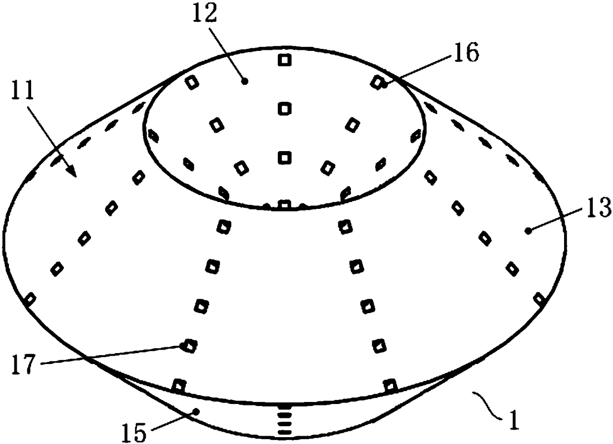
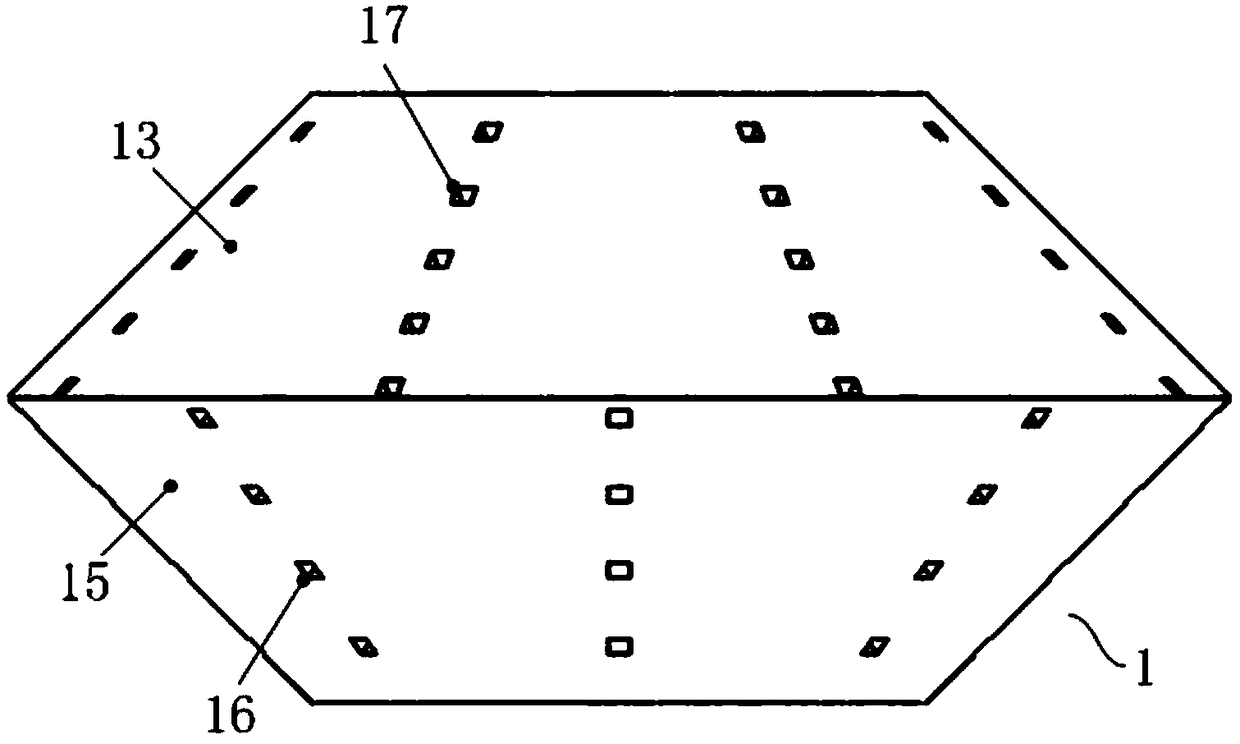
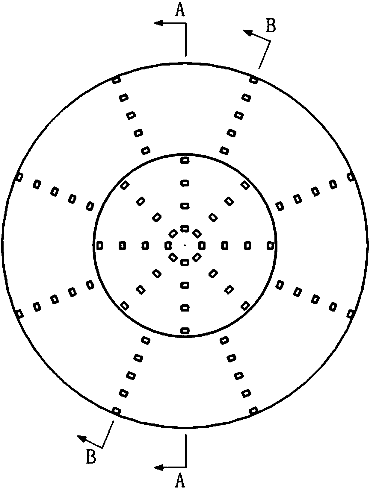
[0044] First refer to Figure 1 to Figure 6 , to describe the first embodiment of the heat exchange core used in the two-way inlet and outlet air ducts of the present invention. in, figure 1 It is a structural schematic diagram of the heat exchange core used for the two-way inlet and outlet air ducts in the first embodiment of the present invention; figure 2 It is the front view of the heat exchange core used for the two-way inlet and outlet air ducts in the first embodiment of the present invention; image 3 It is a top view of the heat exchange core used for the two-way inlet and outlet air ducts in the first embodiment of the present invention; Figure 4 for image 3 Sectional view along A-A direction; Figure 5 for image 3 Sectional view along B-B direction; Image 6 It is a structural schematic diagram of the heat exchanger in the first embodiment of the present invention.
[0045] like Figure 1 to Figure 6 As shown, the present invention firstly provides a hea...
Embodiment 2
[0054] Refer below Figure 8 to Figure 12 , to describe the second embodiment of the heat exchange core used in the two-way inlet and outlet air ducts of the present invention. in, Figure 8 It is a structural schematic diagram of the heat exchange core used for the two-way inlet and outlet air ducts in the second embodiment of the present invention; Figure 9 It is the front view of the heat exchange core used for the two-way inlet and outlet air ducts in the second embodiment of the present invention; Figure 10 for Figure 9 Sectional view along C-C direction; Figure 11 for Figure 9 Sectional view along D-D direction; Figure 12 It is a structural schematic diagram of the heat exchanger in the second embodiment of the present invention.
[0055] like Figure 8 to Figure 12 As shown, the present invention also provides a heat exchange core 3 for a two-way inlet and outlet air duct 4, the two-way inlet and outlet air duct 4 includes an outer tube 41 and a first inner t...
Embodiment 3
[0062] Refer below Figure 13 to Figure 16 , the dual-flow fresh air purification device of the present invention is described. in, Figure 13 It is a structural schematic diagram (without draft tube) of the dual-flow fresh air purification device of the present invention; Figure 14 It is a schematic diagram of the working principle of the dual-flow fresh air purification device of the present invention (without draft tube); Figure 15 It is a schematic structural view of the dual-flow fresh air purification device of the present invention (there is a draft tube); Figure 16 It is a schematic diagram of the working principle of the dual-flow fresh air purification device of the present invention (with a draft tube).
[0063] like Figure 13 and Figure 14 As shown, the dual-flow fresh air purification device 5 of the present invention (hereinafter referred to as the purification device 5) mainly includes a two-way air inlet and outlet duct, an air intake system and an ex...
PUM
 Abstract
Description
Claims
Application Information
 - R&D
- Intellectual Property
- Life Sciences
- Materials
- Tech Scout
- Unparalleled Data Quality
- Higher Quality Content
- 60% Fewer Hallucinations
Browse by: Latest US Patents, China's latest patents, Technical Efficacy Thesaurus, Application Domain, Technology Topic, Popular Technical Reports.
© 2025 PatSnap. All rights reserved.Legal|Privacy policy|Modern Slavery Act Transparency Statement|Sitemap|About US| Contact US: help@patsnap.com