Stable-loop power system

A power supply system and stable technology, applied in control/regulation systems, electrical components, regulating electrical variables, etc., can solve the problems of large variation range of secondary poles and poor loop stability, and achieve high loop stability and reliability. Effect

Active Publication Date: 2018-08-31
AMOLOGIC (SHANGHAI) CO LTD
View PDF4 Cites 3 Cited by
  • Summary
  • Abstract
  • Description
  • Claims
  • Application Information

AI Technical Summary

Problems solved by technology

[0003] However, in the application process of the traditional switching regulator, affected by the large variation range of the load, the variation range of the secondary pole is very large, and the loop stability is poor under the control method of the existing technology

Method used


Image

  • Stable-loop power system
  • Stable-loop power system
  • Stable-loop power system

Examples


Embodiment Construction

[0032] The present invention will be further described below in conjunction with the accompanying drawings and embodiments.

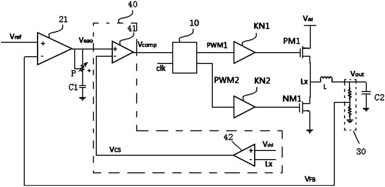
[0033] In a preferred embodiment, as figure 1 As shown, a loop-stabilized power supply system is proposed, which may include:

[0034] A pulse width modulation driver 10, including a control input terminal, a first pulse output terminal and a second pulse output terminal;

[0035] The pulse width modulation driver 10 receives a control signal Vcomp through the control input terminal, and outputs the first pulse signal PWM1 from the first pulse output terminal according to the control signal Vcomp, and outputs the second pulse signal PWM2 from the second pulse output terminal;

[0036] A PMOS transistor PM1, the gate of the PMOS transistor PM1 is connected to the first pulse output terminal;

[0037] An NMOS transistor NM1, the gate of the NMOS transistor NM1 is connected to the second pulse output terminal;

[0038] The drain of the NMOS transistor N...


PUM


Abstract

The invention relates to the technical field of power electronics, in particular to a stable-loop power system. The stable-loop power system comprises a pulse width modulation driver, a P-channel metal-oxide-semiconductor (PMOS) tube, an N-channel metal-oxide-semiconductor (NMOS) tube, a first comparator, a voltage control resistor and a current-limiting protection circuit, wherein the voltage control resistor comprises a first connection end, a second connection end and a central tap control end, the first connection end is connected with a comparison output end, the second connection end isconnected with a first capacitor, the central tap control end is connected with the comparison output end, the voltage control resistor is used for adjusting a resistance value between the first connection end and the second connection end according to a comparison result voltage signal received by the central tap control end, and the resistance value is in negative relation with a voltage value of the comparison result voltage signal. By the stable-loop power system, relatively high loop stability can be ensured, and high reliability is achieved.

Description

technical field [0001] The invention relates to the technical field of power electronics, in particular to a loop-stabilized power supply system. Background technique [0002] With the rapid development of microelectronics technology, step-down switching regulators are widely used in step-down situations due to their simple circuit structure, convenient adjustment, and high reliability; according to different control mechanisms, step-down switching regulators The advantages of the working method and the improvement of the conversion efficiency of the converter are more and more applied to switching power supplies. [0003] However, in the application process of the traditional switching regulator, affected by the large variation range of the load, the variation range of the secondary pole is very large, and the loop stability is poor under the control mode of the prior art. Contents of the invention [0004] In view of the above problems, the present invention proposes a ...

Claims


Application Information

Patent Timeline
Patent Type & Authority Applications(China)
IPC IPC(8): H02M3/158
CPCH02M3/1584
Inventor 樊茂
Owner AMOLOGIC (SHANGHAI) CO LTD
Why Eureka
Try Eureka