
Power supply system with stable loop

a power supply system and stable technology, applied in the field of power and electronic technologies, can solve the problems of poor stability of the switching regulator, and achieve the effect of high loop stability and high reliability

Active Publication Date: 2021-10-28
AMOLOGIC (SHANGHAI) CO LTD
View PDF0 Cites 0 Cited by
  • Summary
  • Abstract
  • Description
  • Claims
  • Application Information

AI Technical Summary

Benefits of technology

The present invention provides a power supply system with a stable loop, which ensures high loop stability and reliability. This results in a more stable and reliable power supply system.

Problems solved by technology

In this case, when in use, the switching regulators have a relatively poor loop stability under the control of the prior art.

Method used


Image

  • Power supply system with stable loop
  • Power supply system with stable loop

Examples


Embodiment Construction

[0046]The present invention will now be described more fully hereinafter with reference to the accompanying drawings, in which exemplary embodiments of the invention are shown. This invention may, however, be embodied in many different forms and should not be construed as limited to the embodiments set forth herein. Rather, these embodiments are provided so that this disclosure will be thorough and complete, and will fully convey the scope of the invention to those skilled in the art. Like reference numerals refer to like elements throughout.

[0047]The terminology used herein is for the purpose of describing particular embodiments only and is not intended to be limiting of the invention. As used herein, the singular forms “a”, “an” and “the” are intended to include the plural forms as well, unless the context clearly indicates otherwise. It will be further understood that the terms “comprises” and / or “comprising,” or “includes” and / or “including” or “has” and / or “having” when used he...


PUM


Abstract

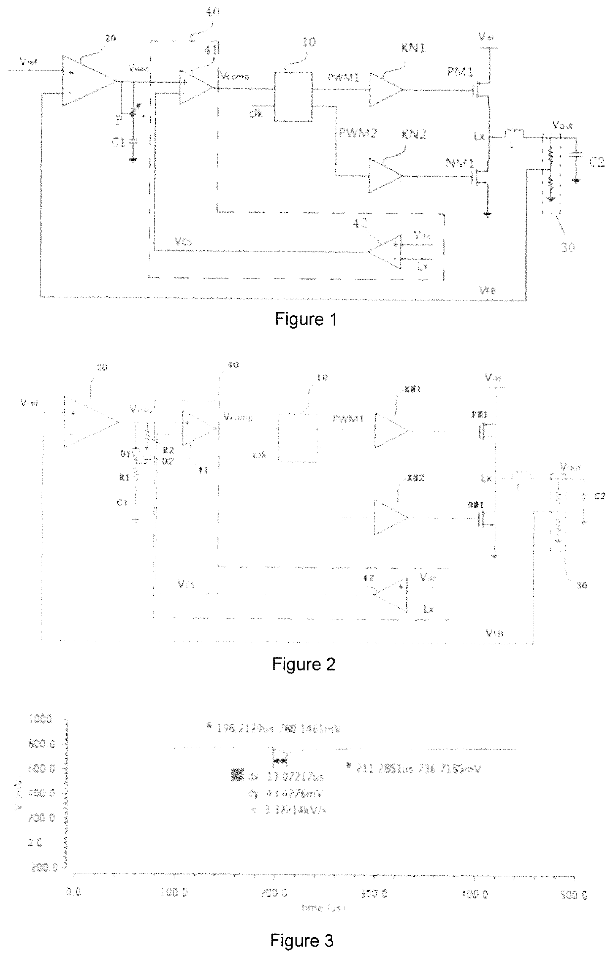
The invention relates to the field of power and electronic technologies, particularly to a power supply system with a stable loop comprising a PMOS transistor, a NMOS transistor, a first comparator and a voltage control circuit connected between a comparison terminal and the ground; wherein, a current-limiting acquisition port is configured to acquire on-state current of the PMOS transistor; and the current-limiting protection circuit outputs an voltage signal of the comparison result as the control signal of the pulse width modulation driver when the acquired on-current state of the PMOS transistor is less than a preset current value; and outputs a turn-off signal for turning off the pulse width modulation driver as the control signal when the acquired on-current state of the PMOS transistor is greater than a preset current value. The present invention has the advantages that relatively high loop stability can be ensured and high reliability is achieved.

Description

BACKGROUND OF THE INVENTION1. Field of the Invention[0001]The invention relates to the field of power and electronic technologies, and more particularly, to a power supply system with a stable loop.2. Description of the Related Art[0002]With the rapid development of the microelectronic technologies, a step-down switching regulator is widely used in step-down occasions by virtue of its simple circuit structure, convenience to adjust and high reliability. Thanks to the operating mode of the step-down switching regulator, conversion efficiency of converters has been improved depending on different control mechanisms, and thus, step-down switching regulators have been widely used in switching power supplies.[0003]However, since the conventional switching regulators are highly influenced in a wide range of load variation, a large variation of secondary poles may occur. In this case, when in use, the switching regulators have a relatively poor loop stability under the control of the prior...

Claims


Application Information

Patent Timeline
Patent Type & Authority Applications(United States)
IPC IPC(8): H02M3/155H02M1/08H03K5/24H02M1/32
CPCH02M3/155H02M1/32H03K5/24H02M1/08H02M3/1588Y02B70/10
Inventor FAN, MAO
Owner AMOLOGIC (SHANGHAI) CO LTD
Learn More