Amplifier circuit having a compensation circuit coupled to an output node of an operational amplifier for improving loop stability

Inactive Publication Date: 2007-12-27
ILI TECHNOLOGY CORPORATION
View PDF1 Cites 1 Cited by
  • Summary
  • Abstract
  • Description
  • Claims
  • Application Information

AI Technical Summary

Benefits of technology

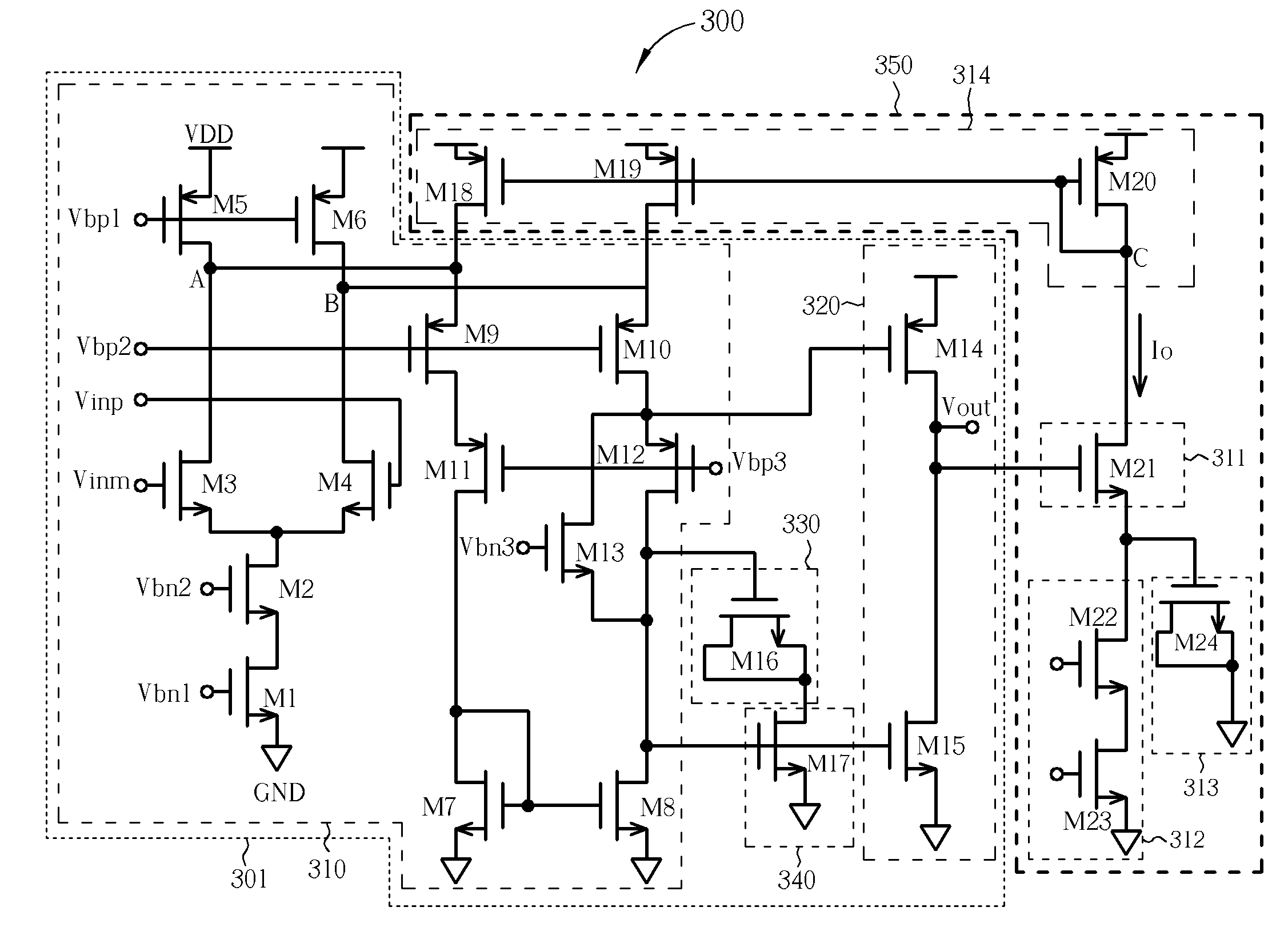
[0010]The amplifier circuit of the present invention relates to a compensation circuit coupled to an output node of an operational amplifier. The compensation circuit generates a voltage-controlled current according to the input voltage of the operational amplifier and feedback the voltage-controlled current to the output node of the first stage amplifier circuit

Problems solved by technology

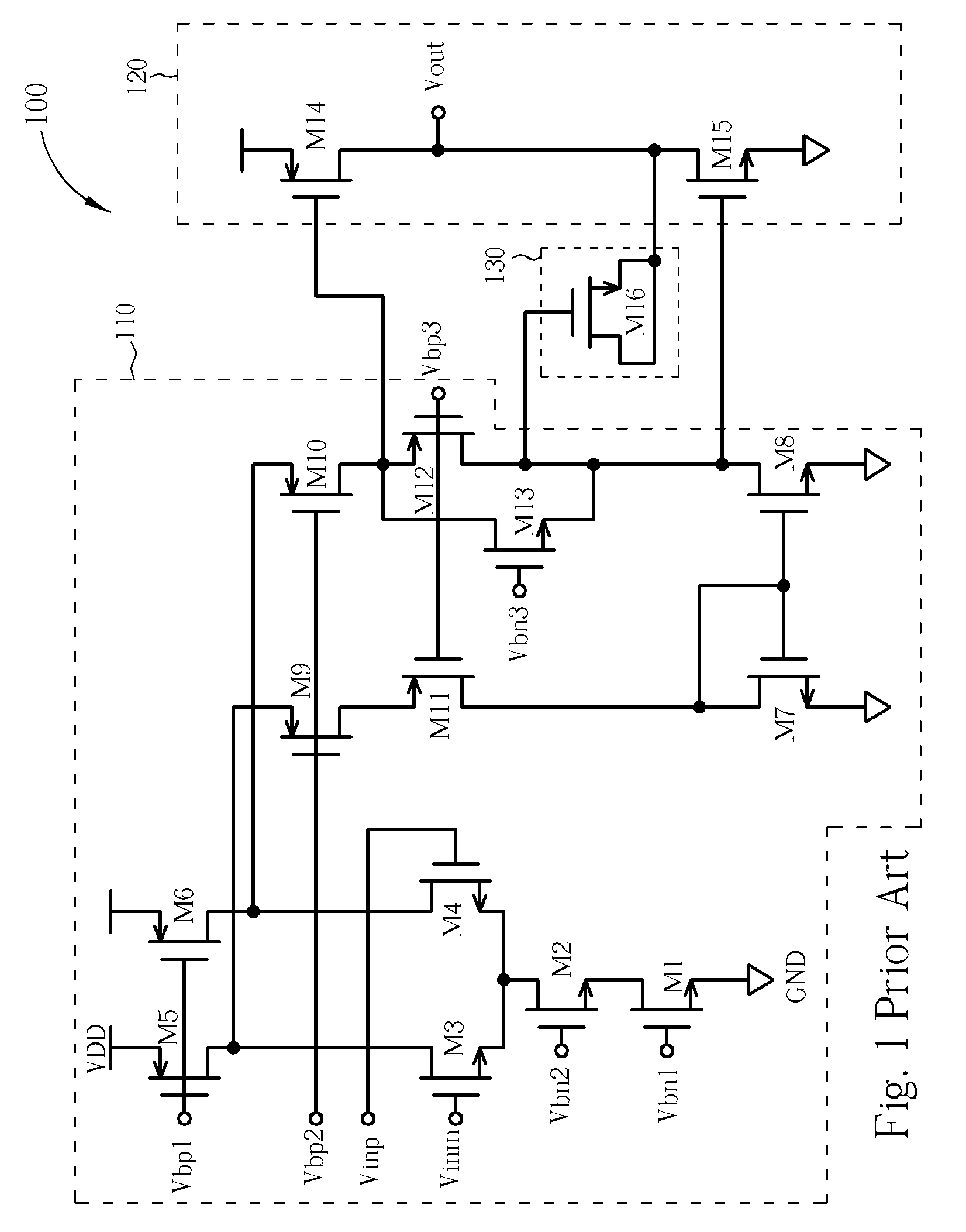
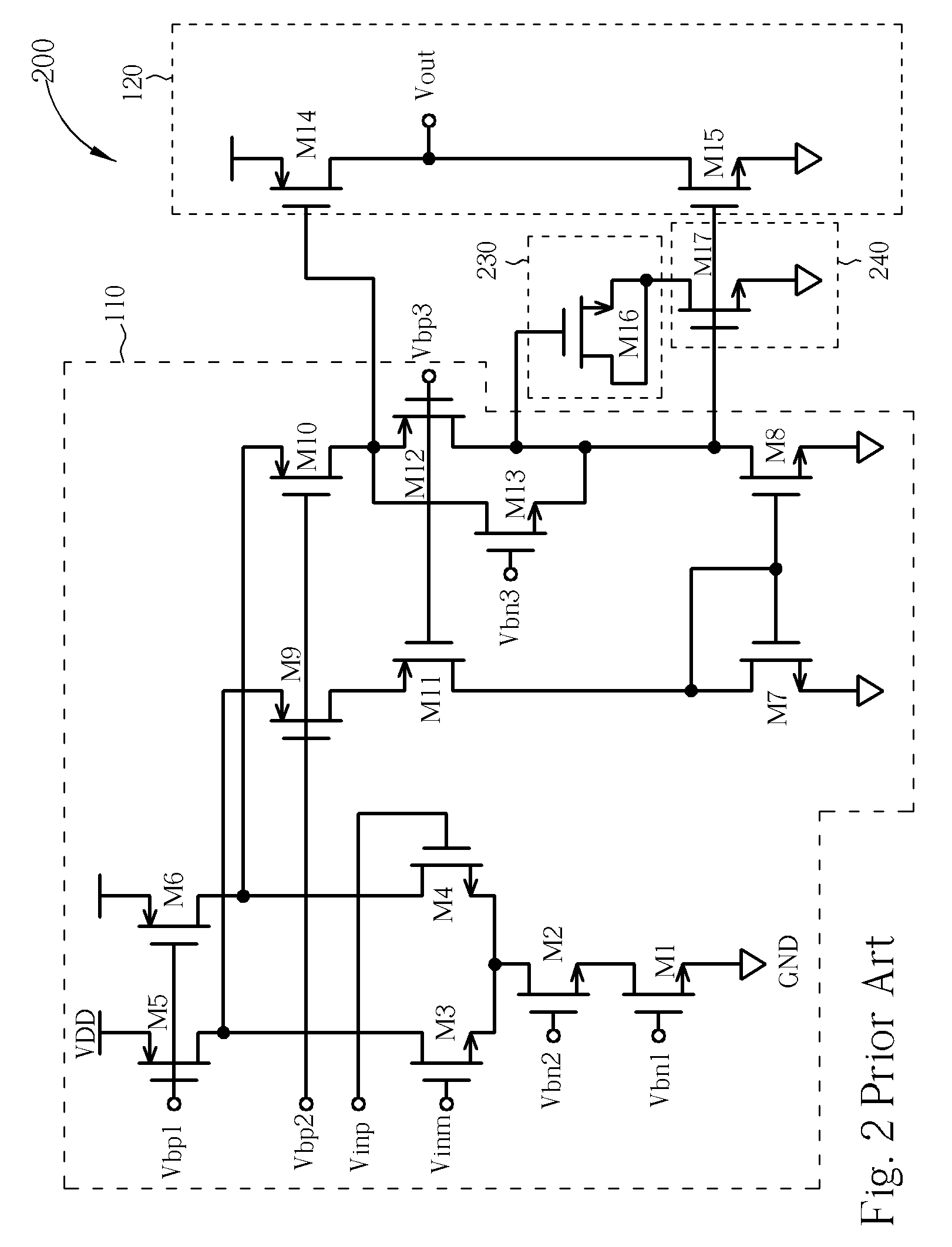
However, the conventional operational amplifier has one problem of insufficient loop stability.
However, while the loading range of the operational amplifier 100 is too large, the cost of the compensation mechanism will also be too high.
However, although the compensation technology, specifically, by utilizing the pole-zero tracking, is able to better resist higher loadin

Method used


Image

  • Amplifier circuit having a compensation circuit coupled to an output node of an operational amplifier for improving loop stability
  • Amplifier circuit having a compensation circuit coupled to an output node of an operational amplifier for improving loop stability
  • Amplifier circuit having a compensation circuit coupled to an output node of an operational amplifier for improving loop stability

Examples


Example

[0016]Certain terms are used throughout the following description and claims to refer to particular system components. As one skilled in the art will appreciate, consumer electronic equipment manufacturers may refer to a component by different names. This document does not intend to distinguish between components that differ in name but not function. In the following discussion and in the claims, the terms “including” and “comprising” are used in an open-ended fashion, and thus should be interpreted to mean “including, but not limited to . . . ” The terms “couple” and “couples” are intended to mean either an indirect or a direct electrical connection. Thus, if a first device couples to a second device, that connection may be through a direct electrical connection, or through an indirect electrical connection via other devices and connections.

[0017]Please refer to FIG. 3. FIG. 3 is a circuit diagram of an amplifier circuit 300 according to an embodiment of the present invention. The ...


PUM


Abstract

An amplifier circuit includes an operational amplifier and a compensation circuit. The operational amplifier includes an amplifying stage for amplifying an input signal to generate an amplifying signal; and an output stage coupled to an output node of the amplifying stage for receiving the amplifying signal and generating an output signal according to the amplifying signal. The compensation circuit is coupled to the output stage and the amplifying stage for generating a compensation signal according to the output signal, and feeding the compensation signal back to the output node of the amplifying stage for compensating the amplifying signal.

Description

BACKGROUND OF THE INVENTION[0001]1. Field of the Invention[0002]The invention relates to an amplifier circuit, and more particularly, to an amplifier circuit having a compensation circuit coupled to an output node of an operational amplifying for improving loop stability.[0003]2. Description of the Prior Art[0004]The operational amplifier has been applied extensively in the field of electrical devices and electronics, such as the inverter amplifier, the integrator, and the filter circuit, to name just a few instances. Generally, the operational amplifier applied in the conventional drive chip is normally a two-stage amplifier that includes a first stage amplifier circuit (amplifying stage) and a second stage output circuit (output stage). The first stage amplifier circuit of the conventional operational amplifier is utilized for enhancing the gain of the operational amplifier; and the second stage output circuit is utilized for driving the capacitive or resistively loading of the op...

Claims


Application Information

Patent Timeline
IPC IPC(8): H03F3/45
CPCH03F1/083H03F3/45192H03F2203/45466H03F2203/45302H03F2200/153
Inventor LIU, MING-HUANGLIU, KAI-MINGHAN, CHEN-HSIENLIN, MENG-YONGLIU, SUNG-ENHUANG, CHI-MO
Owner ILI TECHNOLOGY CORPORATION
Why Eureka
Try Eureka