Material mixing device with multiple mixing chambers

A material mixing and mixing chamber technology, which is applied in the direction of mixers, food science, grain processing, etc., can solve the problems of difficult powder mixing evenly, affecting the mixing effect, and low production efficiency, so as to prevent material clogging, facilitate material mixing, Effect of improving mixing efficiency

Active Publication Date: 2018-09-04
SHENGZHOU YIYUAN INVESTMENT MANAGEMENT
View PDF8 Cites 18 Cited by
  • Summary
  • Abstract
  • Description
  • Claims
  • Application Information

AI Technical Summary

Problems solved by technology

However, generally in food processing, the amount of production is relatively large. The above-mentioned high-efficiency flour mixing and sifting device adopts arc-shaped stirring blades installed in the stirring box for stirring. If the stirring box is set too small, the production efficiency will be low. If the mixing The box is set too large, and it is difficult to mix the powder evenly only by the stirring effect of the arc-shaped stirring blades
[0004] The patent application 201520766551.9 discloses a flour raw material mixer, which has two feeding mechanisms, which are located on both sides of the top of the mixing chamber, and can be loaded with different materials, such as flour and vegetable powder, and then mixed by the mixing mechanism. Mixing. There are three groups of mixing blades in the mixing mechanism, which are respectively distributed on the upper, middle and lower parts of the stirring rod, which can fully mix the flour. The mixed flour falls from the outlet of the mixing bin to the sieve, and then Enter the vibrating sieve through the sieve, because of the vibration of the vibrating sieve, the flour mixture falling on the sieve is sieved through the sieve, and easily enters the inside of the vibrating sieve, and is evenly mixed again under the action of the vibrating sieve, and becomes looser , which is convenient for later kneading; however, the feeding mechanism adopts a screw propulsion device. During the feeding process, due to the extrusion between the materials, the powders are more dense, and it is difficult to mix the raw materials after entering the mixing chamber. , easy to agglomerate, which affects the mixing effect; although it improves the mixing effect by setting multiple sets of mixing blades, when the mixing chamber is too large, the effect is limited, and the problem of powder agglomeration cannot be solved, which affects subsequent production and processing

Method used


Image

  • Material mixing device with multiple mixing chambers
  • Material mixing device with multiple mixing chambers
  • Material mixing device with multiple mixing chambers

Examples


Embodiment 1

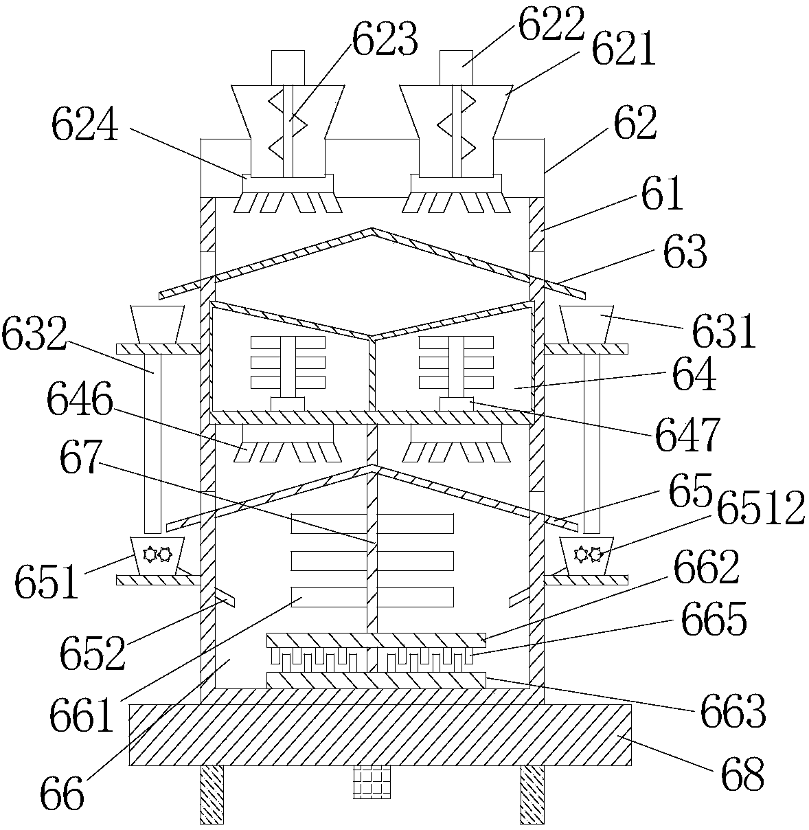
[0026] Such as figure 1As shown, the present embodiment discloses a material mixing device with multiple mixing chambers, including a mixing tank body 61 and a mixing upper cover 62 covered on the mixing tank body 61 , and in the cavity of the mixing tank body 61 A first mixing sieve plate 63, a first mixing chamber 64, a second mixing sieve plate 65, and a crushing / mixing integrated chamber 66 are arranged sequentially from top to bottom. The upper part passes through the crushing / mixing integrated chamber 66 , the second mixing sieve plate 65 and extends into the mixing shaft 67 of the first mixing chamber 64 . Two feeding bins 621 are installed on the mixing upper cover 62, and a feeding motor 622 is installed on the feeding bin 621, and a screw feeding rod 623 is installed in the feeding bin 621, and the feeding motor 622 is connected with the screw feeding rod 623 , the bottom of the feeding chamber 621 is installed with a first spraying device 624 . Such as Figure 4 ...

Embodiment 2

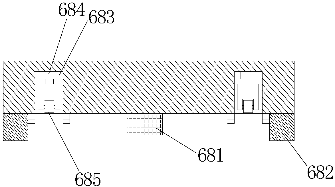
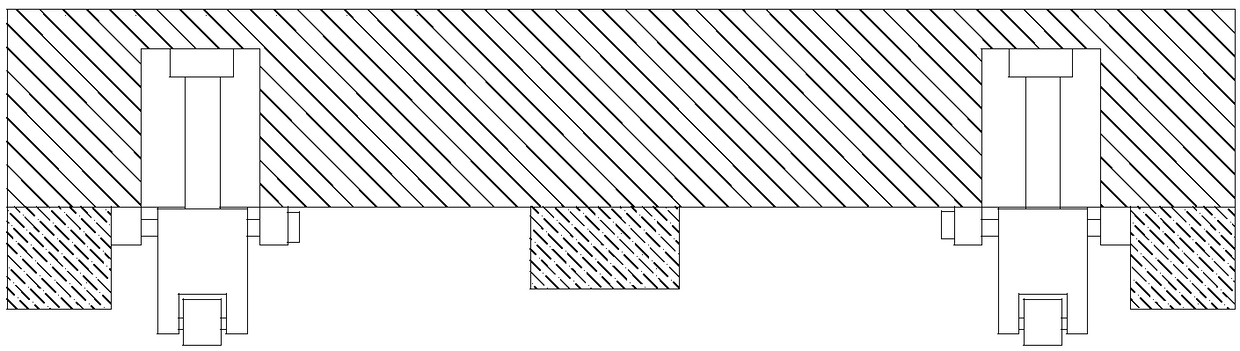
[0030] Such as Figure 1-3 As shown, the difference between this embodiment and the above-mentioned embodiments is that the mixing device also includes a base 68 on which a rotating motor 681 is installed, the rotating motor 681 is connected to the mixing shaft 67, and several supporting legs 682 are installed on the base 68. Around the base 68 are also provided with some accommodation grooves 683, and a vertically arranged mixing cylinder 684 is installed in the accommodation groove 683. The upper end of the mixing cylinder 684 is fixedly connected with the base 68, and the lower end of the mixing cylinder 684 is equipped with universal wheels. 685.

[0031] Traditional material mixing devices generally have a fixed base, which makes it cumbersome and time-consuming to move the entire device. There is also a part of the material mixing device to install moving wheels on the lower part of the base for the convenience of moving, but it vibrates greatly when it moves, and its s...

Embodiment 3

[0033] Such as figure 1 , 6 As shown, the difference between this embodiment and the above-mentioned embodiments is that the first crushing device 651 includes a crushing chamber 6511, and two crushing rollers 6512 that cooperate with each other are installed in the crushing chamber 6511, and crushing shafts are installed on the two crushing rollers 6512. 6513, wherein a crushing motor 6514 is installed on one of the crushing shafts 6513, and transmission teeth 6515 are installed on the two crushing shafts 6513, and the two crushing shafts 6513 are connected by the meshing transmission of the transmission teeth 6515.

[0034] Because two crushing rollers 6512 that cooperate with each other are installed in the crushing chamber 6511, the crushing effect is good. Because the crushing shafts 6513 are installed on the two crushing rollers, and the two crushing shafts 6513 are connected through the meshing transmission of the transmission teeth 6515, through a The pulverizing moto...


PUM


Abstract

The invention discloses a material mixing device with multiple mixing chambers. The device comprises a mixing tank body and a mixing top cover covering the mixing tank body, and a first mixture sieving plate, a first mixing chamber, a second mixture sieving plate and a crushing/mixing integration chamber are sequentially arranged in the cavity of the mixing tank body from top to bottom. A screw feeding rod is mounted in a feeding chamber to prevent wheat flour and corn flour from obstructing the feeding chamber; and a first sprayer is mounted at the lower part of the feeding chamber, and can sprays a material to change a traditional discharging manner, so the material is smoothly discharged, the sprayed material is loose, and can be subsequently mixed easily, and the mixing efficiency is improved.

Description

technical field [0001] The invention relates to the technical field of powder material mixing devices, in particular to a material mixing device with multiple mixing chambers. Background technique [0002] In the production and processing of miscellaneous grains, steamed bread, noodles, etc., it is often necessary to mix flour and corn flour. In general processing, the particle size of flour and corn flour is different. The flour particles are smaller, while the corn flour particles are larger. When corn flour and flour are mixed, problems such as uneven mixing and agglomeration are prone to occur. There is no special device for mixing cornmeal and flour in the prior art, resulting in low mixing efficiency and poor mixing quality when flour and cornmeal are mixed, which in turn affects the taste of food. [0003] The patent application 201720199323.7 discloses a high-efficiency flour mixing and sifting device, which has the functions of stirring, mixing and screening. It in...

Claims


Application Information

Patent Timeline
Patent Type & Authority Applications(China)
IPC IPC(8): B01F13/10B01F15/02B01F15/00B07B9/00B02C4/08B02C7/04
CPCB02C4/08B02C7/04B07B9/00B01F33/5014B01F33/811B01F35/188B01F35/7175
Inventor 朱梁帅曾絮
Owner SHENGZHOU YIYUAN INVESTMENT MANAGEMENT
Why Eureka
Try Eureka