Pneumatic stretching mould

A technology of drawing dies and cylinders, which is applied in the field of stamping machines, can solve problems such as high working intensity, inconvenient disassembly and installation, and inability to continue processing, and achieve the effects of improving processing efficiency, convenient installation and disassembly, and reducing labor intensity

Active Publication Date: 2018-09-04
嘉兴恒益安全服务股份有限公司
View PDF6 Cites 3 Cited by
  • Summary
  • Abstract
  • Description
  • Claims
  • Application Information

AI Technical Summary

Problems solved by technology

[0002] The forming of the existing aluminum bottle cap requires a pneumatic mold for stretching, but the structure of the existing stretching mold is complex, and it is inconvenient to disassemble and install. At the same time, stretching can only be done individually, and the aluminum plate needs to be disassembled and installed repeatedly, and the work intensity is high. , can not be processed continuously, the efficiency is low, it is extremely inconvenient to use, and after stamping and forming, there is a lack of technology to automatically clean the iron filings after stamping, and the iron filings left behind are likely to cause factors such as unsightly surface of the stamping surface

Method used


Image

  • Pneumatic stretching mould
  • Pneumatic stretching mould
  • Pneumatic stretching mould

Examples


Embodiment Construction

[0017] The present invention will be further described below in conjunction with accompanying drawing description and specific embodiment:

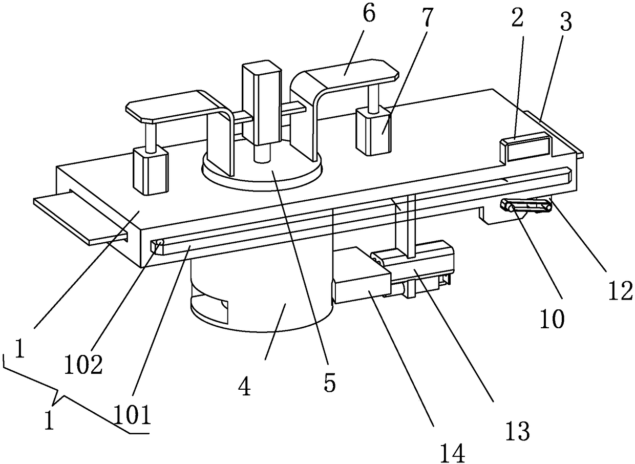
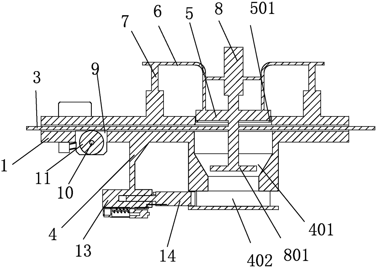
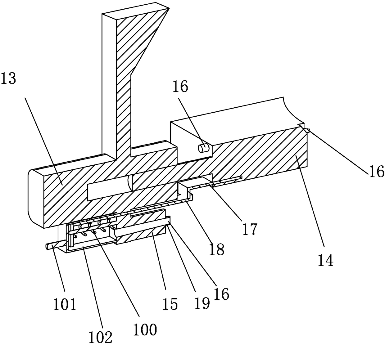
[0018] Such as Figures 1 to 3 A kind of pneumatic drawing die shown, comprises material base 1, is characterized in that the upper surface of described material base 1 is equipped with PLC controller 2, and the input end of described PLC controller 2 is electrically connected with the output end of external power supply , the middle part of the material base 1 is provided with a material cavity in the horizontal direction, the aluminum plate 3 is arranged in the material cavity, the lower surface of the material base 1 is provided with a mold base 4, and the upper surface of the material base 1 and the mold base 4. A pressure opening is provided at the corresponding position, and a first pressure plate 5 is arranged inside the pressure opening. An annular pressure knife 501 is fixed on the edge of the lower surface of the first pressure ...


PUM


Abstract

The invention discloses a pneumatic stretching mould. The pneumatic stretching mould comprises a material base, wherein a PLC is mounted on the upper surface of the material base; the input end of thePLC is electrically connected with the output end of an external power supply; a material cavity in the horizontal direction is arranged in the middle part of the material base; an aluminum board isarranged in the material cavity; and the lower surface of the material base is equipped with a mould base. According to the pneumatic stretching mould disclosed by the invention, a first pressure plate and a second pressure plate stamp and process the aluminum board into an aluminum cover, the first pressure plate has a material cutting function, and continuous stretching operation of the aluminumcover is realized in a mode of matching with horizontal feeding of rollers; the second pressure plate is matched with a shrinkage cavity of the mould base for realizing stretching and forming of thealuminum cover, and the processed aluminum cover is pushed out from the side surface of the mould base through a pushing plate, and is stretched and formed once; a device for automatically clearing scrap iron is arranged at the lower side of a third air cylinder, so that action of clearing up scrap iron can be completed automatically during working, and therefore, a plurality of problems caused byscrap iron residues are reduced, aluminum cover processing efficiency is improved, labor intensity of a worker is reduced, and use is more convenient.

Description

technical field [0001] The invention relates to the technical field of stamping machines, in particular to a pneumatic drawing die. Background technique [0002] The forming of the existing aluminum bottle cap requires a pneumatic mold for stretching, but the structure of the existing stretching mold is complex, and it is inconvenient to disassemble and install. At the same time, stretching can only be done individually, and the aluminum plate needs to be disassembled and installed repeatedly, and the work intensity is high. , can not be processed continuously, the efficiency is low, and it is extremely inconvenient to use. After stamping and forming, there is no technology to automatically clean the iron filings after stamping. [0003] Therefore, the existing drawing die needs to be further improved. Contents of the invention [0004] The object of the present invention is to provide a pneumatic stretching die in order to overcome the deficiencies in the prior art. [...

Claims


Application Information

Patent Timeline
IPC IPC(8): B21D37/10B21D51/48B21D35/00B08B5/02
CPCB08B5/02B21D35/002B21D37/10B21D51/48
Inventor 张利
Owner 嘉兴恒益安全服务股份有限公司
Why Eureka
Try Eureka