
High-freedom-degree mechanical arm structure used for machining

A technology of manipulators and degrees of freedom, applied in the direction of manipulators, manufacturing tools, etc., can solve the problems of space resources occupied by manipulators, and achieve the effect of preventing deviation, improving operation accuracy, and increasing the degree of freedom of work

Inactive Publication Date: 2018-09-04
符立华 +1
View PDF7 Cites 2 Cited by
  • Summary
  • Abstract
  • Description
  • Claims
  • Application Information

AI Technical Summary

Problems solved by technology

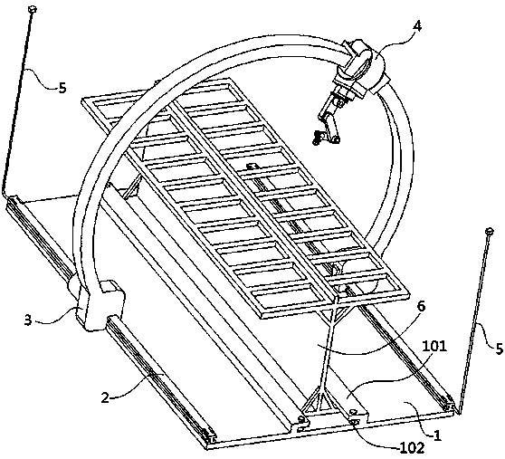
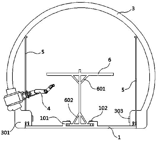
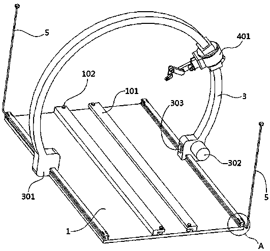
[0004] Aiming at the deficiencies of the prior art, the present invention provides a high-degree-of-freedom manipulator structure for machining. By moving the C-shaped structure of the bracket, the free rotation of the manipulator base is realized, and the space resources occupied by the manipulator operation are solved. The problem

Method used


Image

  • High-freedom-degree mechanical arm structure used for machining
  • High-freedom-degree mechanical arm structure used for machining
  • High-freedom-degree mechanical arm structure used for machining

Examples


Embodiment Construction

[0030] The following will clearly and completely describe the technical solutions in the embodiments of the present invention with reference to the accompanying drawings in the embodiments of the present invention. Obviously, the described embodiments are only some, not all, embodiments of the present invention. Based on the embodiments of the present invention, all other embodiments obtained by persons of ordinary skill in the art without creative efforts fall within the protection scope of the present invention.

[0031] In describing the present invention, it is to be understood that the terms "opening", "upper", "lower", "thickness", "top", "middle", "length", "inner", "surrounding" etc. Indicating orientation or positional relationship is only for the convenience of describing the present invention and simplifying the description, and does not indicate or imply that the components or elements referred to must have a specific orientation, be constructed and operated in a sp...


PUM

PropertyMeasurementUnit
The inside diameter ofaaaaaaaaaa
Outer diameteraaaaaaaaaa
Heightaaaaaaaaaa

Abstract

The invention discloses a high-freedom-degree mechanical arm structure used for machining, and relates to the technical field of industrial machines. The structure comprises a base, sliding rails arefixed to the two sides of one surface of the base, a moving support is in sliding connection to one surfaces of the sliding rails, one surface of the moving support is rotatably connected with a mechanical arm, a positioning device is arranged at one ends of the first sliding rails, a mounting frame is arranged on the first base, sliding bases are arranged on the two ends of the moving support, one surfaces of the sliding bases are in sliding connection with the sliding rails, one surfaces of the sliding bases are fixedly connected with a first drive device, wireless receiving devices are arranged on the opposite surfaces of the sliding bases, the mechanical arm comprises a mechanical arm base, the inner surface of the mechanical arm base is in sliding connection with the moving support, asecond drive device is arranged at the position of one surface of the mechanical arm base, and a fixed plate is fixedly connected to one surface of the mechanical arm base. Through the C structure ofthe moving support, rotatable moving of the mechanical arm base can be achieved, and the advantage of improving the mechanical arm work freedom degree can be achieved.

Description

technical field [0001] The invention relates to the technical field of industrial machinery, in particular to a high-degree-of-freedom mechanical arm structure for machining. Background technique [0002] The robotic arm refers to a high-precision, high-speed dispensing robotic arm. The robotic arm is a complex system with multiple inputs and multiple outputs, highly nonlinear, and strong coupling. Because of its unique operational flexibility, it has been widely used in industrial assembly, safety explosion-proof and other fields. [0003] At present, the mechanical arms used for production and processing on the market are all fixed mechanical arms. When the position of the base is fixed, the free operation of the mechanical arm is realized by rotating the connecting arm or changing the angle between the connecting arms, and the base is fixed. The operating range of the mechanical arm is limited, and the space resources occupied by the operation of the mechanical arm are i...

Claims


Application Information

Patent Timeline
IPC IPC(8): B25J5/04B25J13/08B25J19/00
CPCB25J5/04B25J13/088B25J19/00
Inventor 符立华
Owner 符立华
Learn More