Robot achieving automatic welding of T type welding studs with ceramic rings

A robot and automatic welding technology, applied in welding equipment, auxiliary welding equipment, welding/cutting auxiliary equipment, etc., can solve problems such as affecting the health of welding workers, bone hyperplasia of welding workers, and inability to guarantee welding quality, and achieve significant progress. High performance and industrial practical value, realizing a full range of welding operations, and the effect of high degree of freedom of operation

Pending Publication Date: 2019-09-17
浙江上势自动焊接科技有限公司
View PDF1 Cites 0 Cited by
  • Summary
  • Abstract
  • Description
  • Claims
  • Application Information

AI Technical Summary

Problems solved by technology

The manual welding method not only has the defects of low welding efficiency and unguaranteed welding quality, but also the manual long-term bending operation will seriously affect the health of welders, and it is easy to cause occupational problems such as lumbar muscle strain and bone hyperplasia in welders

Method used


Image

  • Robot achieving automatic welding of T type welding studs with ceramic rings
  • Robot achieving automatic welding of T type welding studs with ceramic rings
  • Robot achieving automatic welding of T type welding studs with ceramic rings

Examples


Embodiment 1

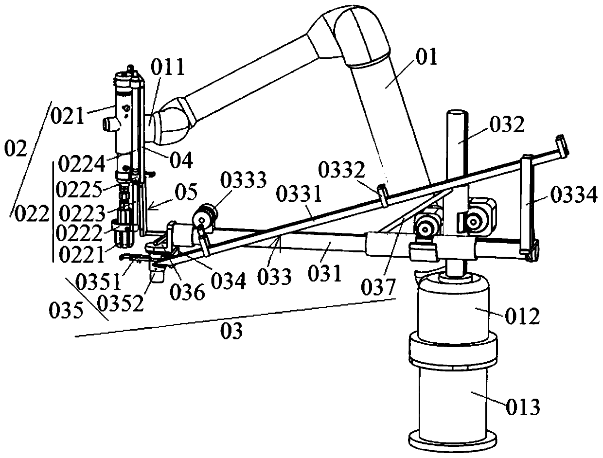
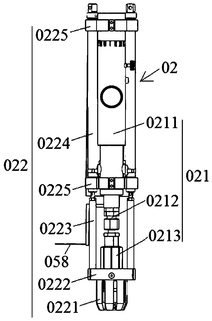
[0051] see figure 1 As shown: a robot for automatic welding of T-shaped welding studs with ceramic rings provided in this embodiment includes a multi-axis mechanical arm 01, an automatic welding gun 02 and an automatic feeding mechanism 03, and the automatic welding gun 02 is fixed on the multi-axis machine The end 011 of the arm, the automatic feeding mechanism 03 includes a crossbeam 031, a vertical column 032, a material clip 033, a discharge assembly 034, a feeding assembly 035 and an L-shaped mounting plate 036, and the crossbeam 031 is connected with the vertical column 032 , the material clip 033 is connected with the crossbeam 031, and the discharge assembly 034 includes a material stopper rod 0340, which is installed on the discharge end of the material clip 033 and can realize telescopic movement, and the material receiving and feeding The assembly 035 includes a transfer clip 0351 and a transfer motor 0352. One end of the transfer clip 0351 is provided with a U-shap...

Embodiment 2

[0072] see Figure 12 As shown, the robot provided in this embodiment to realize the automatic welding of T-shaped welding studs with ceramic rings is only different from the robot described in Embodiment 1 in that: the robot also includes a horizontally moving base 06, a multi-axis mechanical arm The fixed base 013 is fixed on the horizontally movable base 06.

[0073] As a preferred solution, a feeding mechanism 07 can be fixed on the horizontally movable base 06 (the feeding mechanism 07 can adopt the device for realizing automatic feeding of T-shaped welding studs described in the invention patent ZL201620260551.6), for convenience. Clip 033 fast feeding.

[0074] If the height of the horizontally movable base 06 is low, the robot can be made to carry out the welding operation to the workpiece 10 along the walking side (please refer to Figure 13 shown); if the height of the legs of the horizontally moving base 06 is higher than the sum of the height of the workpiece to ...


PUM


Abstract

The invention discloses a robot achieving automatic welding of T type welding studs with ceramic rings. The robot comprises a multi-axis mechanical arm, an automatic welding gun and an automatic feeding mechanism. The automatic welding gun is fixed to the end of the multi-axis mechanical arm. The automatic feeding mechanism comprises a cross beam, a longitudinal vertical column, a feed collet, a discharging assembly, a receiving and feeding assembly and an L-shaped mounting plate. The cross beam is connected with the longitudinal vertical column, and the feed collet is connected with the cross beam. The discharging assembly comprises a blocking rod which penetrates through the discharge end of the feed collet and can achieve telescopic motion. The receiving and feeding assembly comprises a receiving and feeding clamp and a receiving and feeding motor. A U type receiving groove with an opening facing the feed collet is formed in one end of the receiving and feeding clamp, the other end of the receiving and feeding clamp sleeves an output shaft of the receiving and feeding motor, the receiving and feeding motor is fixed to the bottom of the L-shaped mounting plate, and the L-shaped mounting plate is fixedly arranged at the front end of the cross beam. Automatic welding of the T type welding studs with the ceramic rings can be achieved, and the robot is high in working freedom degree, high in universality and high in automation degree.

Description

technical field [0001] The invention relates to a robot for realizing automatic welding of T-shaped welding studs with ceramic rings, and belongs to the technical field of automatic welding. Background technique [0002] T-shaped welding studs, also known as cylindrical head welding studs, have been widely used as shear connectors (also known as shear keys) in steel structures and "steel-concrete" structures in construction and bridge construction. The arc stud welding method is used to plant and weld on steel beams, steel columns and other structures. In addition, in the arc stud welding process, in order to protect the metal melt after the welding stud and the base metal are discharged and melted, it is necessary to set a ceramic ring on each welding stud, and use the high temperature resistance of ceramics to protect the welding melt No leakage to improve welding quality and prevent damage to the torch head caused by ignition of the welding torch and base metal. [0003...

Claims


Application Information

Patent Timeline
Patent Type & Authority Applications(China)
IPC IPC(8): B23K37/02B23K37/00
CPCB23K37/00B23K37/0247B23K37/0252
Inventor 胡长建邓显红
Owner 浙江上势自动焊接科技有限公司
Why Eureka
Try Eureka