Device applied to automatic welding of T-shaped welding stud with ceramic ring

A ceramic ring and welding stud technology is applied in the field of automatic T-shaped welding stud welding devices, which can solve the problems affecting the health of welding workers, the welding quality cannot be guaranteed, and the bone hyperplasia of welding workers, etc., and achieves a high degree of freedom of operation and automation High-level, versatile effects

Pending Publication Date: 2019-09-17
浙江上势自动焊接科技有限公司
View PDF2 Cites 0 Cited by
  • Summary
  • Abstract
  • Description
  • Claims
  • Application Information

AI Technical Summary

Problems solved by technology

The manual welding method not only has the defects of low welding efficiency and unguaranteed welding quality, but also the manual long-term bending operation will seriously affect the health of welders, and it is easy to cause occupational problems such as lumbar muscle strain and bone hyperplasia in welders

Method used


Image

  • Device applied to automatic welding of T-shaped welding stud with ceramic ring
  • Device applied to automatic welding of T-shaped welding stud with ceramic ring
  • Device applied to automatic welding of T-shaped welding stud with ceramic ring

Examples


Embodiment 1

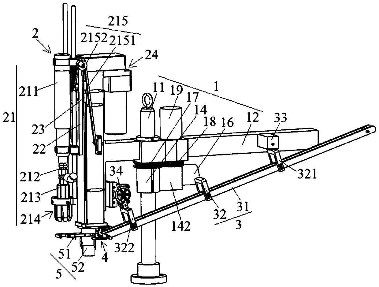
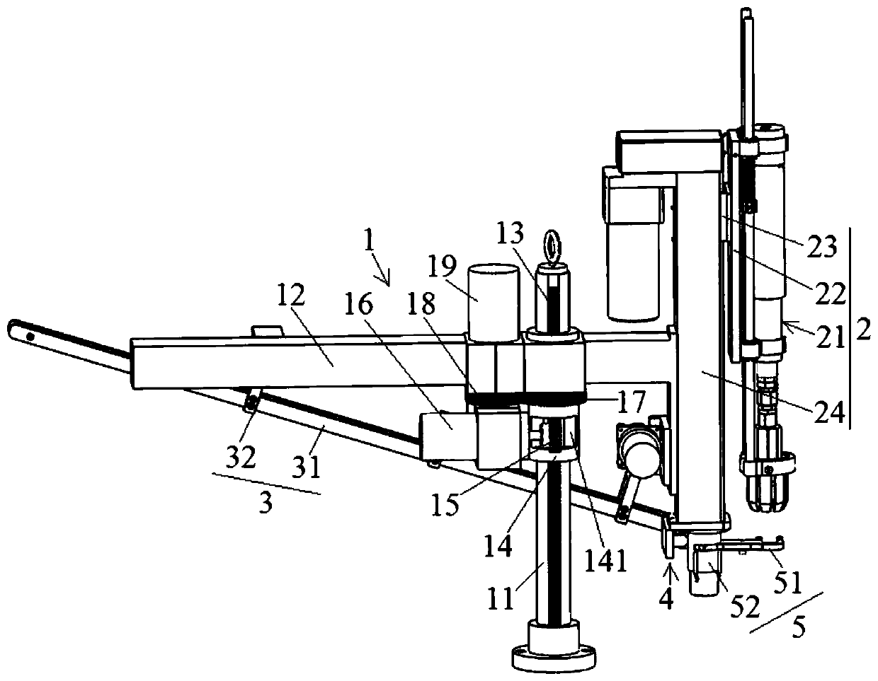
[0063] Please combine figure 1 and figure 2 Shown: This embodiment provides a device for automatic welding of T-shaped welding studs with ceramic rings, including a mounting frame 1, an automatic welding gun 2, a material clamp 3, a feeding assembly 4 and a feeding assembly 5.

[0064] The mounting frame 1 includes a column 11 and a transverse support 12, the transverse support 12 is sleeved on the column 11, and can move up and down on the column 11 and rotate 360 ​​degrees around the column 11 (the specific implementation of the present embodiment It is: a straight line rack 13 is provided in the longitudinal direction of the column 11, and a sliding sleeve 14 that can slide up and down but does not rotate around it is sleeved on the column 11, and the horizontal bracket 12 is rotatably sleeved on the column. On the sliding sleeve 14, the lower part of the sliding sleeve 14 is provided with an opening 141 for the meshing connection between the lifting gear 15 and the linea...

Embodiment 2

[0081] See Figure 11 As shown, the present embodiment provides a device for automatic welding of T-shaped welding studs with ceramic rings. The only difference from the device described in Embodiment 1 is that the device also includes a horizontally moving base 6 and an electrical controller 7 , the rest of the content is the same as described in Example 1.

[0082] Please combine Figure 11 and Figure 12 Shown: described horizontal movement base 6 is made up of horizontal base plate 61 and some universal ball wheels 62 arranged on the bottom of horizontal base plate 61 and 4 groups of wire rope traction mechanisms 63 arranged on horizontal base plate 61, each group of wire rope traction mechanisms 63 Both include a steel wire rope 631, an electric wire rope winch 632 and an alignment sensor 633. The front end of the steel wire rope 631 is provided with a fixed hook 6311. By making the fixed hook 6311 fixed, the electric wire rope winch 632 is then used to rewind the wire ...

Embodiment 3

[0087] See Figure 15 and Figure 16 As shown, the device provided in this embodiment to realize the automatic welding of T-shaped welding studs with ceramic rings is only different from the device described in Embodiment 2 in that the horizontally movable base 6 is composed of a bow-shaped bottom plate 64 and a set Several universal ball wheels 62 at the bottom of the two wings of the arcuate base plate 64 and steel wire rope traction mechanisms 63 symmetrically arranged on the two wings of the arcuate base plate 64 are formed. The front end of the steel wire rope 631 is provided with a fixed hook 6311. By fixing the fixed hook 6311, the electric wire rope winch 632 is used to rewind the wire rope 631 or unwind the wire rope 631 to drive the arcuate base plate 64 to move forward or backward; The bottom end is fixed on the arcuate base plate 64, thereby can realize the walking movement of the whole device of the present invention.

[0088] Depend on Figure 17 and Figure ...


PUM


Abstract

The invention discloses a device applied to automatic welding of a T-shaped welding stud with a ceramic ring. The device comprises an installation frame, an automatic welding gun, a material clamp, a material placement assembly and a material receiving-conveying assembly, wherein the installation frame comprises an upright and a horizontal support; the horizontal support sleeves the upright, can make ascending and descending motion on the upright and can be rotated within 360 DEG around the upright; the automatic welding gun comprises a welding gun main body, a fixation plate of the welding gun main body, a lifting slide block and a vertical lifting mechanism; the upper part of the material clamp is connected to the horizontal support, and the lower part is connected to a shell body of the vertical lifting mechanism; the material placement assembly comprises a material blocking rod which penetrates a discharge end of the material clamp and can realize telescopic motion; and the receiving-conveying assembly comprises a receiving-conveying clamp and a receiving-conveying motor. The device disclosed by the invention has the beneficial effects that the T-shaped welding stud with the ceramic ring can be automatically welded; a full-scope stud welding operation can be realized; especially after configuration of a horizontal movable base, the device can be applied to automatic welding of various welding sites and work pieces; and universality and the automation degree are high.

Description

technical field [0001] The invention relates to a device for realizing automatic welding of T-shaped welding studs with ceramic rings, and belongs to the technical field of automatic welding. Background technique [0002] T-shaped welding studs, also known as cylindrical head welding studs, have been widely used as shear connectors (also known as shear keys) in steel structures and "steel-concrete" structures in construction and bridge construction. The arc stud welding method is used to plant and weld on steel beams, steel columns and other structures. In addition, in the arc stud welding process, in order to protect the metal melt after the welding stud and the base metal are discharged and melted, it is necessary to set a ceramic ring on each welding stud, and use the high temperature resistance of ceramics to protect the welding melt No leakage to improve welding quality and prevent damage to the torch head caused by ignition of the welding torch and base metal. [000...

Claims


Application Information

Patent Timeline
Patent Type & Authority Applications(China)
IPC IPC(8): B23K37/02B23K37/00
CPCB23K37/00B23K37/0247
Inventor 胡长建邓显红
Owner 浙江上势自动焊接科技有限公司
Why Eureka
Try Eureka