
Cooling device for machining and quenching of stepped drill

A cooling device and step drill technology, applied in the direction of quenching device, quenching agent, manufacturing tools, etc., can solve the problems of time-consuming and laborious manual operation, failure to work normally, splashing, etc., to reduce additional consumption, good purging effect, and cooling good effect

Pending Publication Date: 2018-09-04
ZHENGJIANG DANTU DISTRICT NINGBO RUN TOOLS
View PDF0 Cites 0 Cited by
  • Summary
  • Abstract
  • Description
  • Claims
  • Application Information

AI Technical Summary

Problems solved by technology

[0002] Step drill, also known as step drill or pagoda drill, is mainly used for drilling thin steel plates within 3mm. One drill bit can replace multiple drill bits. Holes with different diameters can be processed according to needs, and large holes can be processed at one time. There is no need to replace the drill bit and make positioning holes, etc. Most of the existing cooling devices for step drilling are manually operated, which is time-consuming and labor-intensive, and after the cooling device is cooled, the step drill is adsorbed with cooling oil, which is easy to splash when cleaning with an air nozzle Into the cooling device, it will dirty the cooling device, it is very cumbersome to clean, and the cooling oil sometimes splashes into other parts of the cooling device, causing it to not work properly

Method used


Image

  • Cooling device for machining and quenching of stepped drill
  • Cooling device for machining and quenching of stepped drill
  • Cooling device for machining and quenching of stepped drill

Examples


Embodiment Construction

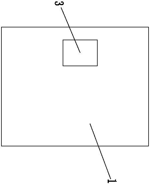
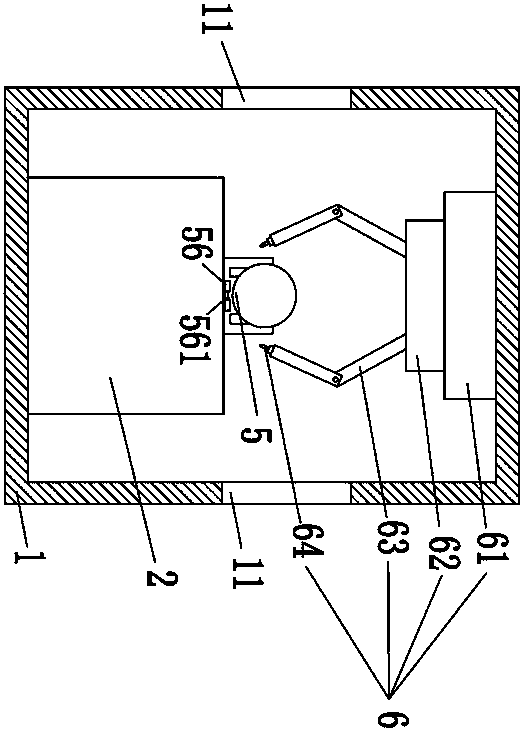
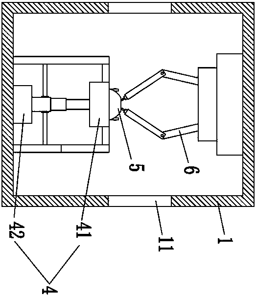
[0023] Such as Figure 1-6 As shown, a cooling device for processing step drill quenching, including a cooling device housing 1, a cooling platform 2 and a PLC controller 3, the cooling platform 2 is arranged in the cooling device housing 1, and is arranged in the cooling device housing 1 bottom, the cooling table 2 is provided with an oil storage tank 21, the oil storage tank 21 is filled with cooling oil, the PLC controller 3 is arranged on the cooling device housing 1, and the cooling device housing 1 There are electric telescopic doors 11 on both sides, and the electric telescopic doors 11 are arranged in the middle of both sides of the cooling device shell 1. The electric telescopic doors 11 on the left side are the feeding end of the cooling device shell 1, and The electric telescopic door 11 is the discharge end of the cooling device housing 1, and the cooling device housing 1 is also provided with a lifting mechanism 4, a telescopic mechanism 5 and an oil removal mecha...


PUM


Abstract

The invention puts forward a cooling device for machining and quenching of a stepped drill. The cooling device comprises a cooling device shell, a cooling table and a PLC, wherein an oil storage poolis arranged in the cooling table, and electric telescopic doors are arranged on the two side faces of the cooling device shell; a lifting mechanism, a telescoping mechanism and an oil removing mechanism are further arranged in the cooling device shell; the lifting mechanism comprises a displacement table and a lifting motor, a sealing block is arranged at the connection between a lifting rod of the lifting motor and the bottom of the oil storage pool, and multiple sealing rings are arranged at the connection between the inner wall of the sealing block and the lifting rod; the oil removing mechanism comprises a fixed base, a motor and mechanical arms, and an air nozzle is arranged at the other end of each mechanical arm; and the telescoping mechanism comprises a telescopic motor, telescopicrods and an oil removing cover, an air blowing opening is formed in the upper side of the oil removing cover, a supporting plate is provided with a flow guide block, and a flow guide groove is formedin the oblique plane of the flow guide block. According to the cooling device, manual feeding and discharging are not required, the stepped drill can be automatically cooled, the stepped drill is blown and washed after cooling, and time and labor are saved.

Description

technical field [0001] The invention relates to the technical field of cooling devices, in particular to a cooling device for quenching step drills. Background technique [0002] Step drill, also known as step drill or pagoda drill, is mainly used for drilling thin steel plates within 3mm. One drill bit can replace multiple drill bits. Holes with different diameters can be processed according to needs, and large holes can be processed at one time. There is no need to replace the drill bit and make positioning holes, etc. Most of the existing cooling devices for step drilling are manually operated, which is time-consuming and labor-intensive, and after the cooling device is cooled, the step drill is adsorbed with cooling oil, which is easy to splash when cleaning with an air nozzle Into the cooling device, the cooling device will be dirty, it is very cumbersome to clean, and the cooling oil sometimes splashes into other parts of the cooling device, causing it to not work prop...

Claims


Application Information

Patent Timeline
IPC IPC(8): C21D1/63C21D1/58C21D9/22
CPCC21D1/58C21D1/63C21D9/22
Inventor 徐启祥
Owner ZHENGJIANG DANTU DISTRICT NINGBO RUN TOOLS
Features
  • Generate Ideas
  • Intellectual Property
  • Life Sciences
  • Materials
  • Tech Scout
  • Unparalleled Data Quality
  • Higher Quality Content
  • 60% Fewer Hallucinations
Learn More