
Contact mode micro accelerometer

A micro-accelerometer and acceleration technology, applied in the direction of measuring acceleration, speed/acceleration/shock measurement, measuring devices, etc., can solve the problems of error, sensor lag error return, etc., achieve high range, reduce lag error, and suppress capacitance saturation Effect

Active Publication Date: 2018-09-04
WENZHOU UNIVERSITY
View PDF17 Cites 0 Cited by
  • Summary
  • Abstract
  • Description
  • Claims
  • Application Information

AI Technical Summary

Problems solved by technology

In addition, the relative movement between the moving electrode and the insulating layer also leads to the generation of friction force
According to a large number of literatures, including the literature on contact mode micro pressure sensors, van der Waals force and friction can cause significant hysteresis error (return error) to the sensor

Method used


Image

  • Contact mode micro accelerometer
  • Contact mode micro accelerometer
  • Contact mode micro accelerometer

Examples


Embodiment Construction

[0019] Embodiments of the present invention will be further described below in conjunction with accompanying drawings:

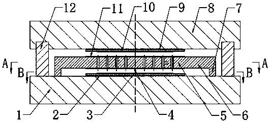
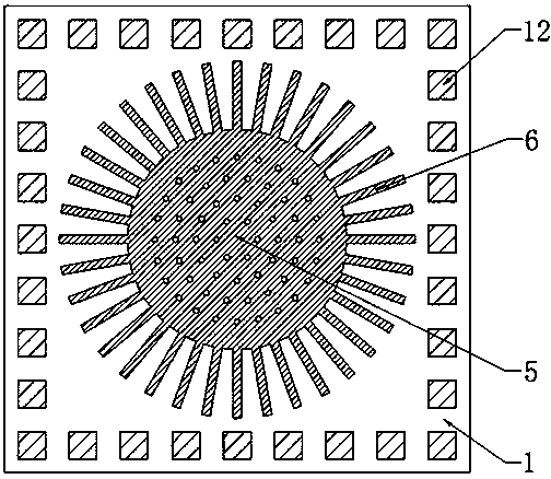
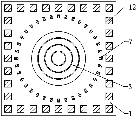
[0020] In an embodiment of the present invention, a contact mode micro-accelerometer includes: a lower base 1, an upper base 8, a support column 12, a thin plate 5, a plurality of support beams 6 and beam anchors are arranged between the lower base 1 and the upper base 8 Point 7, the lower base 1 and the upper base 8 are provided with a lower fixed electrode 2 and an upper fixed electrode 9, and the surfaces of the lower and upper fixed electrodes 2 and 9 are respectively covered with a lower insulating layer 3 and an upper insulating layer 10, and the thin plate The lower and upper surfaces of the 5 are respectively provided with a lower moving electrode 4 and an upper moving electrode 11, and the micro accelerometer has a thin plate 5, the lower moving electrode 4, and the upper moving electrode 11 which are deformed under force simultaneously but are not c...


PUM


Abstract

The invention provides a contact mode micro accelerometer which comprises a lower substrate and an upper substrate. A supporting column, a thin plate, a plurality of supporting beams and anchor pointsof the beams are arranged between the lower substrate and the upper substrate. The lower substrate and the upper substrate are provided with lower and upper fixed electrodes. The surfaces of the fixed electrodes are covered with insulating layers. The upper and lower surfaces of the thin plate are provided with upper and lower moving electrodes. The micro accelerometer has a first working state in which the thin plate and the moving electrodes are deformed by force but are not in contact with the insulating layer and a second working state in which the thin plate and the moving electrodes aredeformed by force and are in contact with the insulating layers. According to the contact mode micro accelerometer, a principle that the accelerometer causes the deformation of the moving electrodesand thus the capacitance between the fixed electrodes is changed is used to work. Through the insulating layers on the fixed electrodes, the short circuit of the moving and fixed electrodes is prevented, the insulating layers provide support for a movable structure, thus the measurement of the high acceleration can be realized, and the capacitance saturation of the sensor can be effectively suppressed by a combined structure of the beams and the round thin plate.

Description

technical field [0001] The invention relates to the field of micro-electromechanical systems, in particular to a contact mode micro-accelerometer. Background technique [0002] Accelerometers are widely used in many fields such as industry, military, aviation, and daily life. According to the working principle, micro accelerometers can be divided into capacitive, piezoresistive, piezoelectric and so on. Among them, the capacitive type has the advantages of low power consumption, fast response, and high sensitivity. Its working principle is: a variable capacitor is composed of a fixed electrode and a moving electrode, and the moving electrode is located on the acceleration sensitive structure and moves due to the acceleration force. The magnitude of the acceleration can be known by measuring the capacitance between the moving and fixed electrodes. Traditionally, the active structure of capacitive micro accelerometers mainly adopts a comb structure or a beam-mass structure c...

Claims


Application Information

Patent Timeline
Patent Type & Authority Applications(China)
IPC IPC(8): G01P15/125
CPCG01P15/125
Inventor 李凯彭志辉
Owner WENZHOU UNIVERSITY
Learn More