Power distribution network pole-mounted automatic switch adopting electronic sensor

A voltage sensor and current sensor technology, which is applied to substations, circuits, electrical components installed on the column, etc., can solve the disputes over the responsibility of secondary equipment manufacturers, the small dynamic range of voltage sensor measurement, compatibility and scalability. It can solve problems such as poor exchangeability, and achieve the effect of increasing distribution network line loss management and feeder automation functions, improving anti-condensation performance, and improving equipment integration.

Pending Publication Date: 2018-09-04
STATE GRID HUNAN ELECTRIC POWER +2
View PDF6 Cites 9 Cited by
  • Summary
  • Abstract
  • Description
  • Claims
  • Application Information

AI Technical Summary

Problems solved by technology

The current automation design and transformation of pole-mounted switches in the distribution network mainly have the following problems: First, the interface of the secondary equipment does not match, and the compatibility, scalability, and interchangeability are poor; the disputes over the responsibility of the manufacturers of the secondary equipment are not clear; the lack of line loss measurement Function; equipment condensation phenomenon exists; traditional electromagnetic current and voltage sensors have small dynamic range and narrow frequency band, and additional signal conversion equipment is required when connecting with digital secondary equipment

Method used


Image

  • Power distribution network pole-mounted automatic switch adopting electronic sensor
  • Power distribution network pole-mounted automatic switch adopting electronic sensor
  • Power distribution network pole-mounted automatic switch adopting electronic sensor

Examples


Embodiment Construction

[0018] The present invention will be further described below in conjunction with example and accompanying drawing.

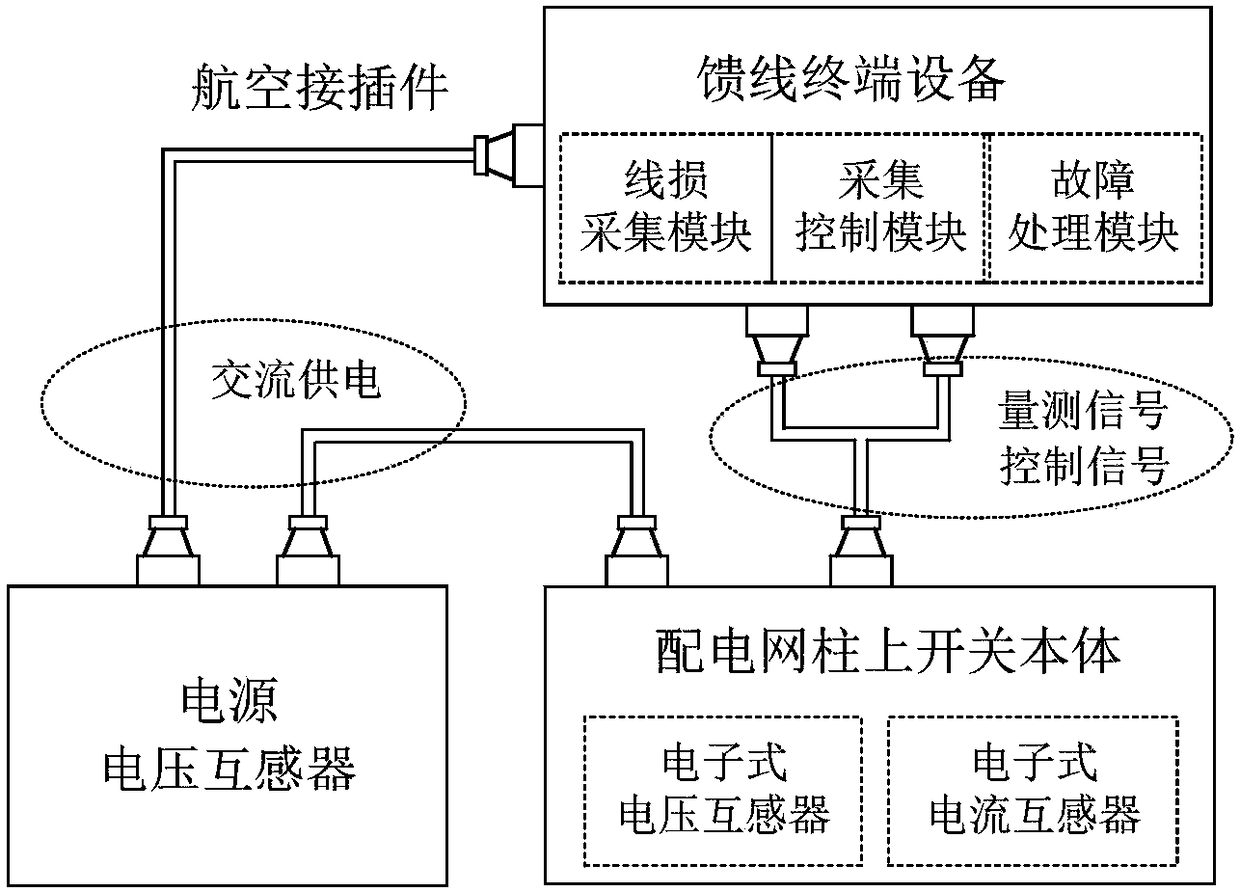
[0019] Overall structure of the present invention is as figure 1 As shown, it is composed of switch body on distribution network column, feeder terminal equipment, power supply voltage transformer, aviation connector and so on.

[0020] Design of the main body of the switch on the pole of the distribution network: a three-phase common box structure, SF6 gas insulation, vacuum arc extinguishing, and composite insulation for the external insulation; the integrated structure of the operating mechanism and the main body is adopted, and it is built in a closed gas box; Military-grade aviation socket, the aviation socket is equipped with an insulating sealing cover to protect the interface; the protection level of the shell is IP67; the pole-mounted switch has built-in electronic voltage sensors and electronic current sensors, which are used to collect three-phase vol...


PUM


Abstract

The invention discloses a power distribution network pole-mounted automatic switch adopting an electronic sensor. The switch comprises a switch device, a feeder terminal and a power supply voltage transformer which are mutually connected through cables, wherein the switch device comprises a switch body, an electronic voltage sensor and an electronic current sensor, and the electronic voltage sensor and the electronic current sensor are used for collecting voltage and current state information of the switch body. The power distribution network pole-mounted automatic switch has the technical effects that by utilizing the design of the power distribution network pole-mounted switch simultaneously having measurement, protection and metering functions, the operation and maintenance quality andefficiencies of the pole-mounted switch can be effectively improved, the field mounting and debugging are convenient, and the power failure time is greatly shortened; by adopting the electronic sensor, the current and voltage sampling precisions are increased to metering levels, so that the switch can meet the requirements on fault detection, measurement, metering and the like; by adding distribution network damage management and feeder automation functions, the operation level of distribution equipment is increased; and primary and secondary equipment are connected through an aviation connector, so that the compatibility and the sealing property of an interface are improved.

Description

technical field [0001] The invention relates to an automatic switch on a power distribution network column using an electronic sensor. Background technique [0002] With the development of computer and digital technology, the power system has begun to turn to automation, digitization, and intelligence, and the demand for switchgear has gradually changed to modularization, miniaturization, multi-function, and maintenance-free. The current automatic design and transformation of pole-mounted switches in the distribution network mainly has the following problems: First, the interface of the secondary equipment does not match, and the compatibility, scalability, and interchangeability are poor; the responsibility disputes between the manufacturers of the first and secondary equipment are not clear; there is a lack of line loss measurement Function; there is equipment condensation; traditional electromagnetic current and voltage sensors have a small measurement dynamic range and n...

Claims


Application Information

Patent Timeline
Patent Type & Authority Applications(China)
IPC IPC(8): H02B5/02H01R13/52
CPCH01R13/52H01R13/521H01R13/5213H02B5/02
Inventor 冷华朱吉然唐海国龚汉阳张志丹陈宏刘海峰郭文明彭春柳李红青陈幸
Owner STATE GRID HUNAN ELECTRIC POWER
Why Eureka
Try Eureka