Staggered sieve plate installation structure of circular flowing type sieve plate tower

A technology of installation structure and sieve plate tower, which is applied in the direction of distillation separation, chemical instruments and methods, separation methods, etc., and can solve the problems of high purity requirements of rectification, high cost, and many material ports.

Pending Publication Date: 2018-09-07
杭州杭氧低温液化设备有限公司
View PDF4 Cites 0 Cited by
  • Summary
  • Abstract
  • Description
  • Claims
  • Application Information

AI Technical Summary

Problems solved by technology

However, the existence of throttling errors leads to uncertainty in the orientation of the trays, which not only greatly reduces the economy of the tower and its peripheral equipment, but also restricts the use of circulation tray technology in the field of large and extra-large air separation for complex processes and materials. The development of more ports and higher requirements for distillation purity
There are many researchers in the field of rectification towers in the world who are devoted to the research of throttling error. In the end, some of them are locked in to use the method of manufacturing actual measurement to determine the size of the throttling error, and temporarily determine the orientation of the nozzle to arrange the pipeline. The other part solves the problem of the influence of throttling error by developing or using other structural sieve plates to eliminate the circulation type sieve plate. These two methods are time-consuming, laborious, costly, and even discard the essence of the circulation type sieve plate. Avoid the throttling error problem of the circulating sieve plate

Method used


Image

  • Staggered sieve plate installation structure of circular flowing type sieve plate tower
  • Staggered sieve plate installation structure of circular flowing type sieve plate tower
  • Staggered sieve plate installation structure of circular flowing type sieve plate tower

Examples


Embodiment

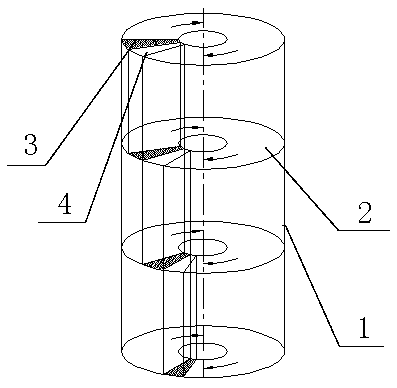
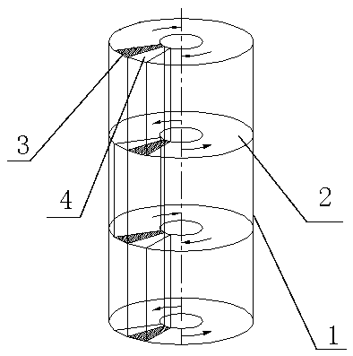
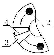
[0013] Embodiment: Based on the design of the circulation type sieve tray tower, the design of the k-th sieve plate and the k+1-th sieve plate reverse flow direction, and the design positions of the liquid receiving tank and the downcomer are changed alternately.

[0014] During the installation process, ensure that the liquid receiving tank of the kth floor tray is aligned with the downcomer position of the k+1th layer, and ensure that the liquid receiving tank in the splitter tower and the downcomer in the vertical direction are basically consistent in the top view installation angle position, Reduce assembly deviation.

[0015] The staggered circulation sieve plate splitter tower of the present invention makes the internal circulation liquid flow alternately in forward and reverse directions, and can well solve the restriction caused by the throttling error. Through the product test verification, the rectification efficiency of the new staggered circulation tower is higher ...


PUM


Abstract

The invention relates to a staggered sieve plate installation structure of a circular flowing type sieve plate tower. The structure comprises a tower body; multiple circular flowing sieve plates are installed on the upper and lower sides of the interior of the tower body and comprise the clockwise circular flowing sieve plates and the counterclockwise circular flowing sieve plates; the flowing direction of every two sieve plates installed between the adjacent upper and lower layers is completely opposite, and that is to say that one of the two sieve plates is the clockwise circular flowing sieve plate, and the other one of the two sieve plates is the counterclockwise circular flowing sieve plate. Tower plate liquid receiving grooves are formed in the circular flowing sieve plates, tower plate downcomers are arranged adjacent to one sides of the tower plate liquid receiving grooves, and circular flowing liquid flows from the outer sides of the liquid receiving grooves to the outer sidesof the downcomers and then enter the downcomers; the downcomers of the circular flowing sieve plates on the upper layer are aligned with the liquid receiving grooves of the circular flowing sieve plates on the lower layer, and the liquid receiving grooves of the circular flowing sieve plates on the upper layer are aligned with the downcomers of the circular flowing sieve plates on the lower layer. The structure has the advantages that the structure is simple, installation is convenient, the rectification effect of a circular flowing type shunt tower can be substantially improved, correspondingly the energy consumption of the tower and peripheral equipment is reduced, and the production cost is saved.

Description

technical field [0001] The invention relates to a staggered sieve plate installation structure of a circulation type sieve plate tower, belonging to the technical field of air separation devices. Background technique [0002] Circulation-type sieve tray towers are widely used in air separation units. Compared with other sieve tray towers, they have higher efficiency and a wider load adjustment range. They are the most cost-effective sieve tray towers in terms of energy consumption and economy. For example, figure 1 shown. However, the existence of throttling errors leads to uncertainty in the orientation of the trays, which not only greatly reduces the economy of the tower and its peripheral equipment, but also restricts the use of circulation tray technology in the field of large and extra-large air separation for complex processes and materials. The development of more ports and higher requirements for distillation purity. There are many researchers in the field of recti...

Claims


Application Information

Patent Timeline
Patent Type & Authority Applications(China)
IPC IPC(8): B01D3/22B01D3/26
CPCB01D3/22B01D3/26
Inventor 何仙来杨修玲斯航军
Owner 杭州杭氧低温液化设备有限公司
Why Eureka
Try Eureka