Laser welding automatic following protective gas jetting blowing system

A protective gas and laser welding technology, which is applied in laser welding equipment, welding equipment, metal processing equipment, etc., can solve the problems of affecting welding quality, inability to melt effectively, and poor adjustment accuracy, so as to improve the effectiveness of blowing and improve the accuracy The effect of sex and maintenance effectiveness

Inactive Publication Date: 2018-09-07
BAOSHAN IRON & STEEL CO LTD
View PDF7 Cites 6 Cited by
  • Summary
  • Abstract
  • Description
  • Claims
  • Application Information

AI Technical Summary

Problems solved by technology

[0002] Two cold-rolled acid-rolled laser welding machines, mainly used for welding hot-rolled steel strips with a thickness of 2mm-3mm and a hardness of HR30Te between 42-65. The output mirror of the laser source body of the welding machine has an output spot diameter of 22mm and a laser beam with a power of 8KW. , the laser has relatively good deep penetration, but when welding molten steel, a large amount of plasma cloud will be generated, which will cause it to be unable to effectively melt the subsequent strip steel and produce pores and virtual welds, so it is necessary to use protective gas to blow off the plasma cloud. The equipment for blowing off the laser welding plasma cloud is the protective gas blowing device. The blowing device is installed

Method used


Image

  • Laser welding automatic following protective gas jetting blowing system
  • Laser welding automatic following protective gas jetting blowing system
  • Laser welding automatic following protective gas jetting blowing system

Examples


Embodiment Construction

[0022] The specific implementation manner of the present invention will be further described below in conjunction with the drawings and specific examples.

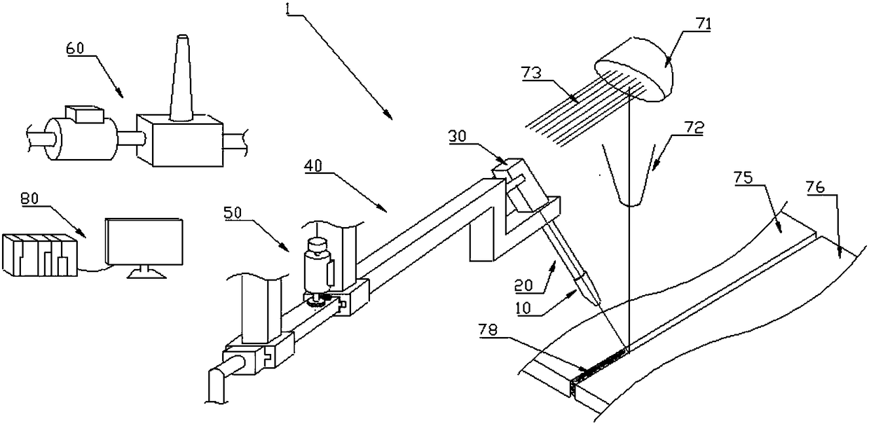
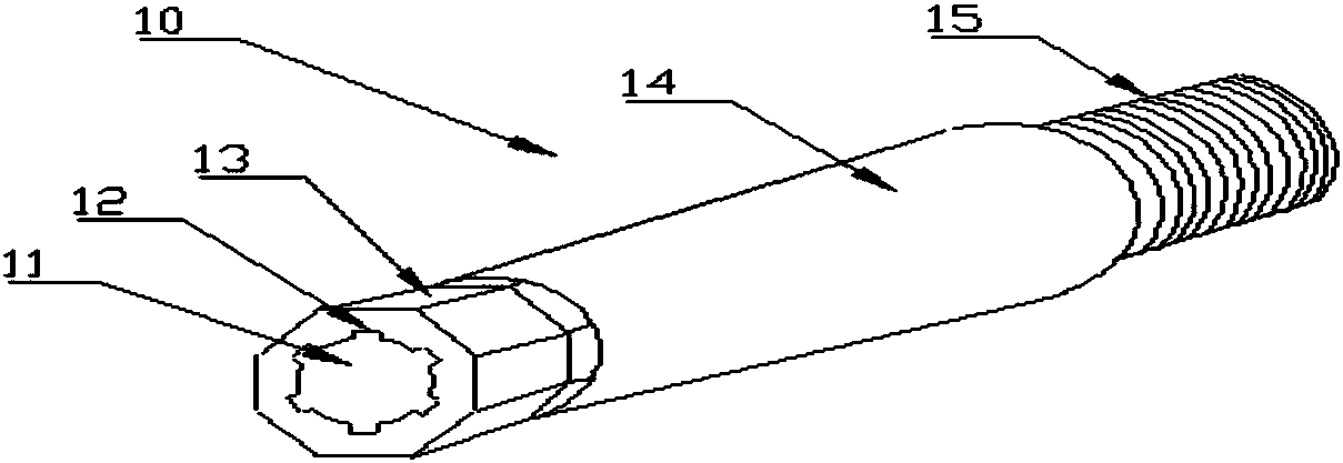
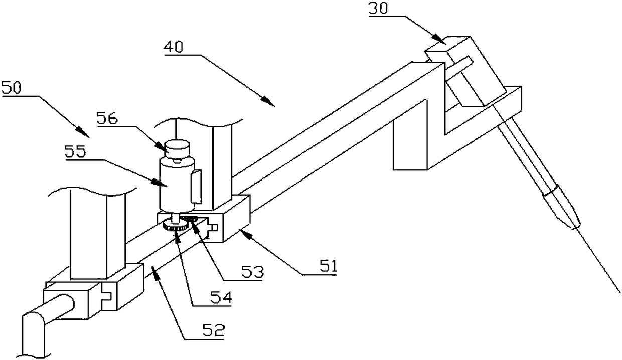
[0023] The invention provides a system device for laser welding self-following protective gas injection, which is improved in terms of equipment component structure and control mode. The gas is injected from the spray rod and the nozzle, and the actual position of the welding seam sprayed by the protective gas is accurately indicated. It is displayed on the CRT screen through the position detection system and the coordinated control components. The image analysis software calculates and judges whether the position of the protective gas injection is The middle position of the welding seam is the laser focus position. If the measured deviation exceeds the range, it can automatically follow the focus position for adjustment and correction; the flow and pressure detection control part detects whether the sprayed protective gas ...


PUM


Abstract

The invention discloses a laser welding automatic following protective gas jetting blowing system. The laser welding automatic following protective gas jetting blowing system comprises a jetting blowing device provided with a jetting rod, the jetting rod is connected with a jetting head, a jetting blowing passage of the jetting rod is provided with a laser positioning component, after protective gas analog signals sent by the laser positioning component are sent out from a jetting mouth, an actual position of protective gas jetting blowing is labeled out in a form of laser projection, the system further comprises a position detection device, a coordination control device and a flow quantity and pressure detection control device, the welding line middle position which finally needs to be jetted and blown is taken as a target position, the position detection device is used for detecting the distance or overlap degree of the actual position and the target position, the coordination control device is used for maintaining overlap or automatic following of the two positions, a flow quantity and pressure detection control component is used for detecting the unimpeded situation of the protective gas jetting blowing passage and performing flow quantity adjustment according to the detected result, a jetting hole of the jetting head is of a round hole shape, the hole wall of the jetting hole is provided with grooves which are evenly arranged along the periphery wall, and the groove bottom of each groove is square.

Description

technical field [0001] The invention relates to protective gas injection during laser welding of equipment such as laser welding machines, and is particularly suitable for a carbon dioxide laser welding protective gas injection system for laser welding machines of high-speed continuous rolling mills in iron and steel enterprises. Background technique [0002] Two cold-rolled acid-rolled laser welding machines, mainly used for welding hot-rolled steel strips with a thickness of 2mm-3mm and a hardness of HR30Te between 42-65. The output mirror of the laser source body of the welding machine has an output spot diameter of 22mm and a laser beam with a power of 8KW. , the laser has relatively good deep penetration, but when welding molten steel, a large amount of plasma cloud will be generated, which will cause it to be unable to effectively melt the subsequent strip steel and produce pores and virtual welds, so it is necessary to use protective gas to blow off the plasma cloud. ...

Claims


Application Information

Patent Timeline
IPC IPC(8): B23K26/14B23K26/142
CPCB23K26/14B23K26/142
Inventor 陈杰黄佩杰吴贇豪
Owner BAOSHAN IRON & STEEL CO LTD
Why Eureka
Try Eureka