Smoke and dust suction device and laser production equipment

A vacuum device, laser technology, applied in the direction of laser welding equipment, printing equipment, welding equipment, etc., can solve the problems of not being compatible with PCB production lines, poor smoke and dust suction effect, low efficiency, etc., to avoid the influence of smoke and dust, Good effect and high efficiency

Pending Publication Date: 2018-09-07
深圳市振华兴科技有限公司
View PDF0 Cites 2 Cited by
  • Summary
  • Abstract
  • Description
  • Claims
  • Application Information

AI Technical Summary

Problems solved by technology

[0002] Laser equipment will generate a lot of smoke during marking, engraving, coding, cutting, etc., and will leave PCB dust after the end. Existing smoking and dust collection devices are installed near the PCB board for smoking and suction. Dust, because it is fixed near the PCB board, and the laser head marking, engraving, coding, cutting and other operations are moved anywhere on the PCB board. Engraving, coding, cutting movement, its smoke and dust suction effect is poor, low efficiency, not suitable for compatible with PCB production line

Method used


Image

  • Smoke and dust suction device and laser production equipment
  • Smoke and dust suction device and laser production equipment
  • Smoke and dust suction device and laser production equipment

Examples


Embodiment Construction

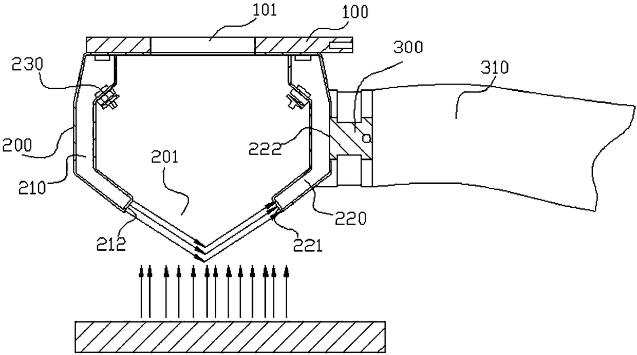
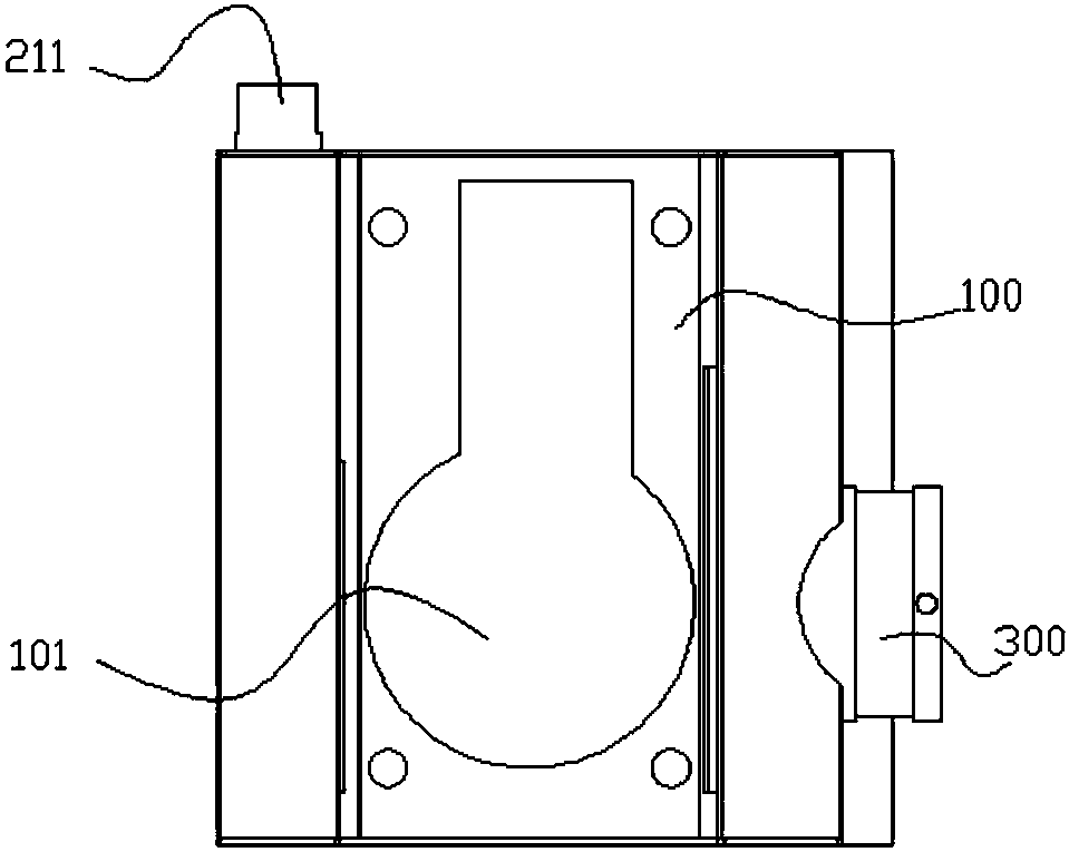
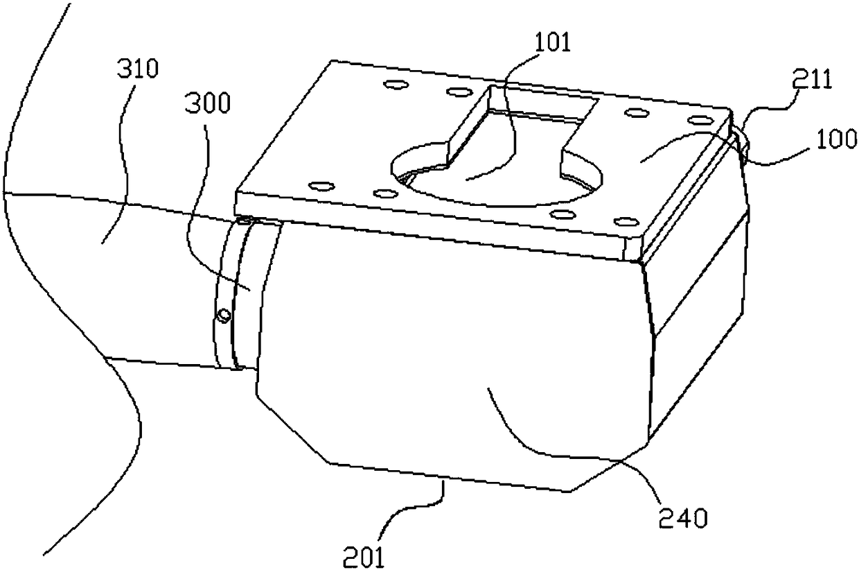
[0026] see Figure 1~3 The smoke and dust suction device of the present invention includes a fume hood main body 200 and a fixing plate 100, the fume hood main body 200 is installed under the fixing plate 100, and the light outlet 101 that allows the laser to pass through is provided on the fixing plate 100, and the fume hood The main body 200 is a cover structure surrounded by surroundings. The interior of the smoke hood main body 200 is a space communicating with the light outlet 101 . The hood structure of the fume hood main body 200 is provided with a blowing channel 210 and a suction channel 220 which are independent of each other, and the blowing channel 210 is provided with an air inlet 211 connected to an external blowing device and a dust blowing port 212 connected thereto. The suction channel 220 is provided with a suction port 222 connected to external suction equipment and a dust suction port 221 connected thereto. The dust blowing port 212 and the dust suction por...


PUM


Abstract

The invention discloses a smoke and dust suction device which comprises a smoke hood main body and a fixed plate; the smoke hood main body is installed under the fixed plate; the fixed plate is provided with a light outlet through which laser light passes; the smoke hood main body is of a hood body structure with the periphery enclosed; the interior of the smoke hood main body is a space which iscommunicated with the light outlet; a main body opening is formed in the side, opposite to the light outlet, of the smoke hood main body; the smoke hood main body is internally provided with an air blowing channel and a suction channel which are mutually independent; the air blowing channel is provided with an air inlet which is connected with external air blowing equipment and a dust blowing holewhich is communicated with the air inlet; the suction channel is provided with an air suction hole which is connected with external suction equipment and a dust suction hole which is communicated with the air suction hole; the dust blowing hole and the dust suction hole are communicated to the main body opening; and the fixed plate is installed on a second sliding plate of laser production equipment, and the second sliding plate is installed on a first sliding plate which can slide along an x axis and can slide along a y axis relative to the first sliding plate. The smoke and dust suction device provided by the invention is good in smoke and dust suction effect, flexible to move and high in efficiency.

Description

【Technical field】 [0001] The invention relates to auxiliary equipment for laser processing, in particular to a smoking and vacuuming device and laser production equipment used in laser processing and production. 【Background technique】 [0002] Laser equipment will generate a lot of smoke during marking, engraving, coding, cutting, etc., and will leave PCB dust after the end. Existing smoking and dust collection devices are installed near the PCB board for smoking and suction. Dust, because it is fixed near the PCB board, and the laser head marking, engraving, coding, cutting and other operations are moved anywhere on the PCB board. Engraving, coding, cutting movement, the smoke and dust suction effect is poor, the efficiency is low, and it is not suitable for compatibility with PCB production lines. [0003] Therefore, it is necessary to provide a high-efficiency smoking and vacuuming device that is compatible with the PCB production line, completes smoking and dust collect...

Claims


Application Information

Patent Timeline
Patent Type & Authority Applications(China)
IPC IPC(8): B23K26/142B41J29/12
CPCB23K26/142B41J29/12
Inventor 廖怀宝
Owner 深圳市振华兴科技有限公司
Why Eureka
Try Eureka