Convenient foundation pit supporting frame and supporting method thereof

A foundation pit support and portable technology, which is applied in excavation, foundation structure engineering, construction, etc., can solve the problems that the pile row cantilever cannot meet the safety requirements of the foundation pit, the dismantling work is not very convenient, and the main shaft inertia moment is quite different. , to facilitate follow-up demolition work, avoid engineering quality problems, and reduce the effect of using

Pending Publication Date: 2018-09-07
TIANJIN JIANCHENGJIYE GRP
View PDF7 Cites 0 Cited by
  • Summary
  • Abstract
  • Description
  • Claims
  • Application Information

AI Technical Summary

Problems solved by technology

[0002] The existing foundation pit support forms (methods) mainly include grading, gravity retaining wall, soil nail wall, pile row, underground diaphragm wall, reverse arch wall, etc. Sometimes they can be used alone or in combination. Due to different geological conditions , the support forms adopted are also different. Under the form of pile row support, because the surrounding environment of the foundation pit is complex, and there are important protection objects on the ground and underground, the design of the pile row cantilever (anti-slide pile) cannot meet the safety requirements of the foundation pit (requirement ), it is necessary to add auxiliary measures such as horizontal supports to control the displacement and deformation of the foundation pit soil during excavation and construction
The existing technology generally uses prefabricated piles as oblique support points. Although there is no need for support in the horizontal direction to save materials, it is not very convenient to handle subsequent demolition work.
Because the section size of I-beam is relatively high and narrow, although it can be applied to foundation pit support, the moment of inertia of the two main axes of the section is quite different, so it can only be used directly in the plane of its web
It is not suitable for construction under axial compression or perpendicular to the web plane, which limits its application range.

Method used


Image

  • Convenient foundation pit supporting frame and supporting method thereof
  • Convenient foundation pit supporting frame and supporting method thereof
  • Convenient foundation pit supporting frame and supporting method thereof

Examples


Embodiment Construction

[0036] It should be noted that, in the case of no conflict, the embodiments of the present invention and the features in the embodiments can be combined with each other.

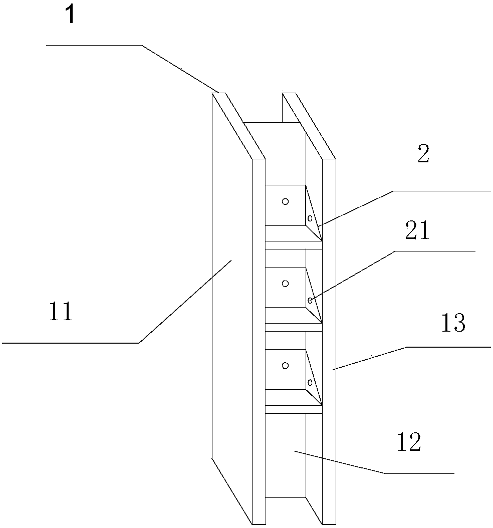
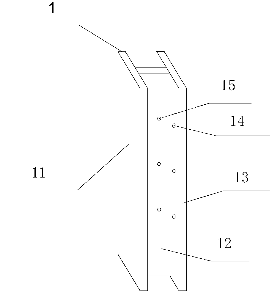
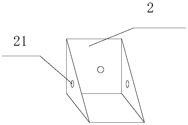
[0037] In describing the present invention, it should be understood that the terms "center", "longitudinal", "transverse", "upper", "lower", "front", "rear", "left", "right", " The orientations or positional relationships indicated by "vertical", "horizontal", "top", "bottom", "inner" and "outer" are based on the orientations or positional relationships shown in the drawings, and are only for the convenience of describing the present invention and Simplified descriptions, rather than indicating or implying that the device or element referred to must have a particular orientation, be constructed and operate in a particular orientation, and thus should not be construed as limiting the invention. In addition, the terms "first", "second", etc. are used for descriptive purposes only, and should not be understood ...


PUM


Abstract

The invention provides a convenient foundation pit supporting frame and a supporting method thereof. The convenient foundation pit supporting frame comprises a supporting frame body and an embedded part, wherein the supporting frame body is of an integral structure with the I-shaped cross section and comprises a left side plate, a web and a right side plate; the left side plate and the right sideplate are respectively and fixedly arranged at the two sides of the web; a plurality of side plate connecting parts are uniformly distributed on the inner walls of the left side plate and the right side plate; a plurality of web connecting parts are uniformly distributed on the web; the web connecting parts and the side plate connecting parts are identical in height; the embedded part is of a triangular prism structure with a right angled triangle cross section; and fixed parts connected to the web connecting parts and the side plate connecting parts are arranged on the three right angle surfaces of the embedded part. The convenient foundation pit supporting frame and the supporting method thereof have the beneficial effects that the convenient foundation pit supporting frame is simple instructure, can be prefabricated in advance, is convenient to produce and transport, causes the site construction to be time-saving and labor-saving, facilitates the construction of workers, meanwhilefacilitates the fallow-up disassembly work and greatly improves construction efficiency.

Description

technical field [0001] The invention belongs to the field of foundation pit support, and in particular relates to a portable foundation pit support frame and a support method thereof. Background technique [0002] The existing foundation pit support forms (methods) mainly include grading, gravity retaining wall, soil nail wall, pile row, underground diaphragm wall, inverted arch wall, etc. Sometimes they can be used alone or in combination, depending on the geological conditions. , the support forms adopted are also different. Under the form of pile support, because the surrounding environment of the foundation pit is complex, and there are important protection objects on the ground and underground, the design of the pile row cantilever (anti-slide pile) cannot meet the safety requirements of the foundation pit (requirement ), and auxiliary measures such as horizontal support must be added to control the displacement and deformation of the foundation pit soil during excavati...

Claims


Application Information

Patent Timeline
Patent Type & Authority Applications(China)
IPC IPC(8): E02D17/04
CPCE02D17/04
Inventor 李刚崔凤祥刘永超刘洁
Owner TIANJIN JIANCHENGJIYE GRP
Why Eureka
Try Eureka