Ball bottom prism and recessed cavity blade tip capable of inhibiting turbine tip leakage flow

A prismatic and concave cavity technology, applied in the field of spherical bottom prism concave cavity blade tip, can solve the problems of weakening leakage flow inhibition, complicated top end zone flow, increasing turbine aerodynamic loss, etc., to achieve good control of blade tip leakage flow, large The effect of enhanced size, flow obstruction effect

Inactive Publication Date: 2018-09-07
HARBIN INST OF TECH
View PDF3 Cites 4 Cited by
  • Summary
  • Abstract
  • Description
  • Claims
  • Application Information

AI Technical Summary

Problems solved by technology

With the increase of the high-performance turbine load, another problem that cannot be ignored: with the increase of the turbine load, the lateral pressure gradient in the cascade channel increases, and the gap between the turbine blade tip and the casing Existence, leading to more obvious gap leakage flow from the pressure surface to the suction surface of the moving blade tip, resulting in more complex flow in the top end zone and incre

Method used


Image

  • Ball bottom prism and recessed cavity blade tip capable of inhibiting turbine tip leakage flow
  • Ball bottom prism and recessed cavity blade tip capable of inhibiting turbine tip leakage flow
  • Ball bottom prism and recessed cavity blade tip capable of inhibiting turbine tip leakage flow

Examples


Embodiment Construction

[0028] It should be noted that, in the case of no conflict, the embodiments of the present invention and the features in the embodiments can be combined with each other.

[0029] The invention will be described in detail below with reference to the accompanying drawings and examples.

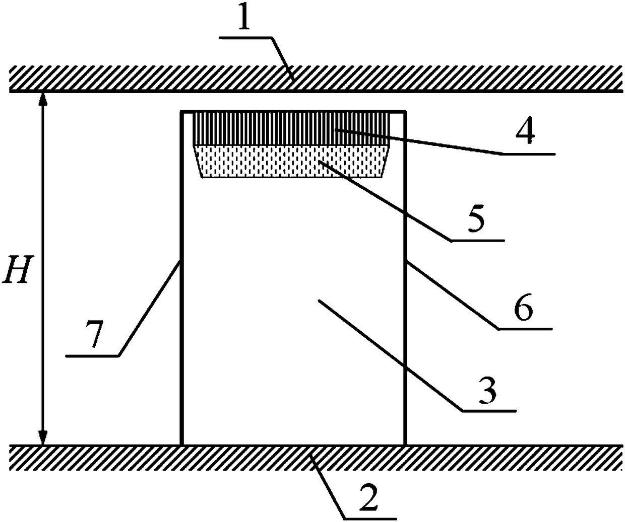
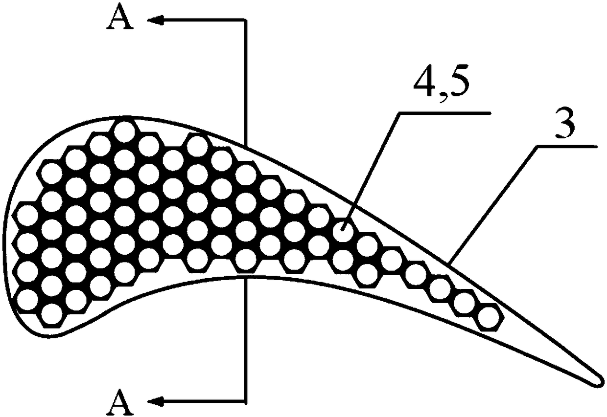
[0030] Such as figure 1 As shown, the present invention is applied in the turbine moving blades. The turbine moving blades 3 are installed on the hub 2, and the cascade flow passage is formed between the casing 1 and the hub 2. 6 and 7 represent the leading edge lines and the On the trailing edge line, a number of prismatic concave cavities 4 are arranged at the position of the blade tip from the leading edge to the trailing edge, and a spherical bottom structure 5 is combined on the lower surface of each prismatic concave cavity 4 to form a prismatic spherical bottom combined concave cavity .

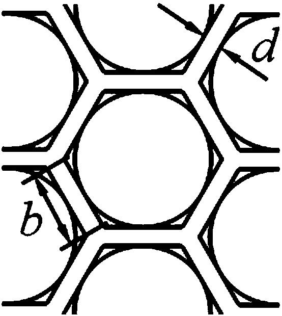
[0031] combine figure 2 and Figure 3a , Figure 3b , which is the design of the specific arran...


PUM


Abstract

The invention provides a ball bottom prism and recessed cavity blade tip capable of inhibiting a turbine tip leakage flow. A plurality of prism type recessed cavities are formed in a blade tip of a turbine moving blade from the front edge to the rear edge of the turbine moving blade; a ball bottom structure of which the circular section is internally tangent with the lower bottom surface of the corresponding prism type recessed cavity is assembled at the bottom surface of each prism type recessed cavity; and a ratio of the maximum height of the prism type recessed cavity to the blade height is0.5-4%. A vortex structure is formed in each single recessed cavity and develops to a gap in the single recessed cavity, so that gap kinetic energy is dissipated, at the same time small-size pneumatic barriers are formed, and the leakage flow resistance is increased. Ball bottom prism and recessed cavity assembled structures allow fluid in recessed cavities to act on the ball bottom wall surfacesalong tangent lines basically, and due to smooth arc-shaped transition of the ball bottom structures, the vortex development resistance is reduced, so that vortexes formed in the cavities develop more completely and have larger sizes, the inhibition effect on the flow in the gaps is improved, and a better effect of controlling the tip leakage flow can be further achieved.

Description

technical field [0001] The invention belongs to the technical field of turbines, and in particular relates to a spherical-bottom prismatic concave-cavity blade top for suppressing leakage flow at the top of a turbine. Background technique [0002] The turbine is one of the three core components of the gas turbine engine. Its function is to convert the gas enthalpy of high-temperature and high-pressure gas into gas kinetic energy to do work on the turbine blades, and then output mechanical work. With the increase of the high-performance turbine load, another problem that cannot be ignored: with the increase of the turbine load, the lateral pressure gradient in the cascade channel increases, and the gap between the turbine blade tip and the casing Existence makes the gap leakage flow from the pressure surface to the suction surface of the rotor blade tip more obvious, which brings more complex flow in the top end zone and increases the aerodynamic loss of the turbine. Especia...

Claims


Application Information

Patent Timeline
IPC IPC(8): F01D11/08F01D5/20F01D9/00
CPCF01D5/20F01D9/00F01D11/08
Inventor 陈浮俞建阳付云峰
Owner HARBIN INST OF TECH
Why Eureka
Try Eureka