
Staggered variable electrode giant electrorheological fluid damper

A technology of giant electrorheological fluid and damper, applied in gas-liquid shock absorber, shock absorber, shock absorber, etc., can solve the problems of non-adjustable damping, lag in progress of giant electrorheological fluid material, and few dampers, etc. Achieving the effect of large damping effect and increasing the adjustable range

Active Publication Date: 2018-09-07
SHANGHAI UNIV
View PDF6 Cites 13 Cited by
  • Summary
  • Abstract
  • Description
  • Claims
  • Application Information

AI Technical Summary

Problems solved by technology

[0009] However, there are relatively few studies on the structural design and application of the damper, and its progress lags behind the research on the characteristics of the giant electrorheological fluid material itself.
Most of the existing automobile dampers are hydraulic dampers, which have the characteristics of non-adjustable damping
In addition, most of the very few giant electrorheological fluid dampers are unipolar plates, and they are in the stage of theoretical research. Compared with the complex electric field of staggered and adjustable multi-plates, their adjustable range is still very limited

Method used


Image

  • Staggered variable electrode giant electrorheological fluid damper
  • Staggered variable electrode giant electrorheological fluid damper
  • Staggered variable electrode giant electrorheological fluid damper

Examples


Embodiment Construction

[0030] The technical solutions in the embodiments of the present invention will be clearly and completely described below with reference to the accompanying drawings in the embodiments of the present invention. Obviously, the described embodiments are only a part of the embodiments of the present invention, but not all of the embodiments. Based on the embodiments of the present invention, all other embodiments obtained by persons of ordinary skill in the art without creative efforts shall fall within the protection scope of the present invention.

[0031] The purpose of the present invention is to provide a giant ER fluid damper with staggered variable electrodes to solve the problems existing in the prior art, so that the electric field in the slit on the piston is distributed under the same voltage due to the staggered electrode polarity. Produces a greater damping effect.

[0032] In order to make the above objects, features and advantages of the present invention more clea...


PUM


Abstract

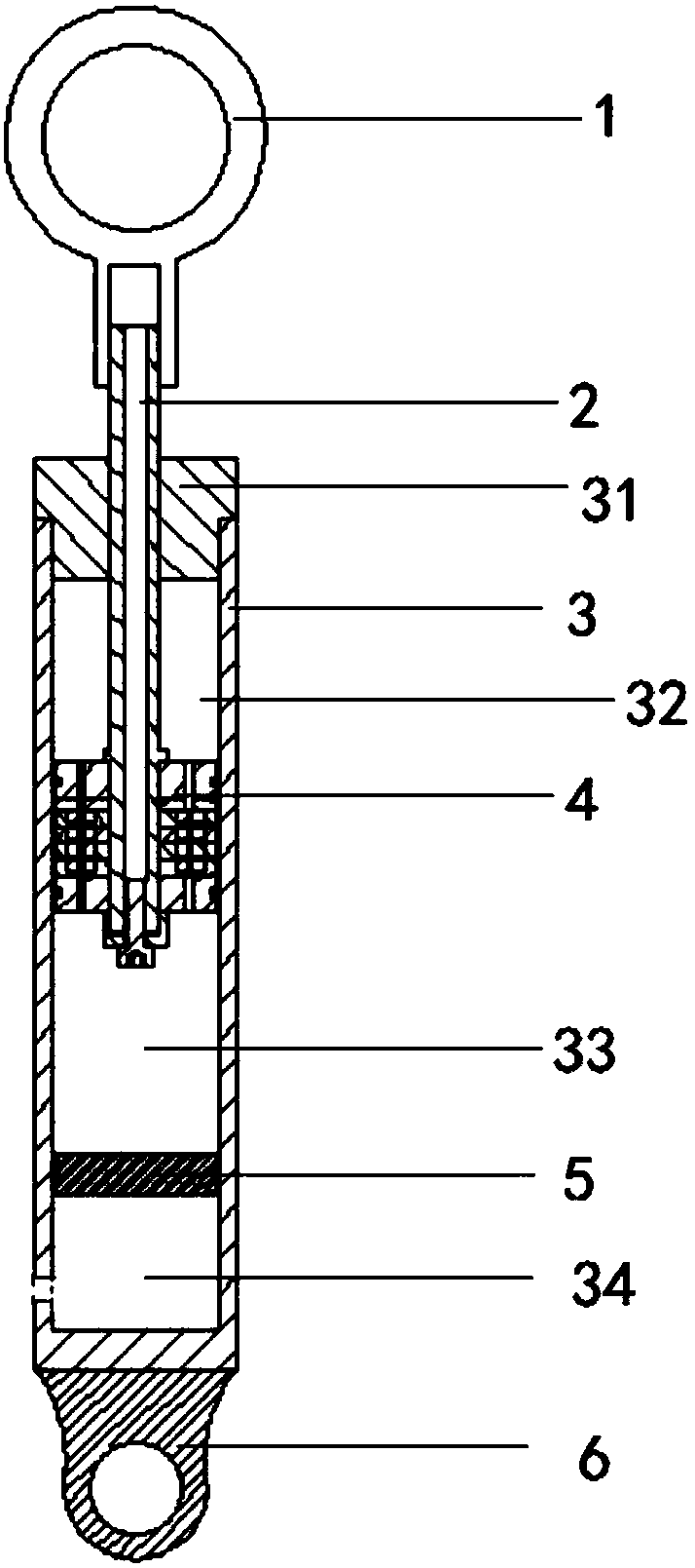
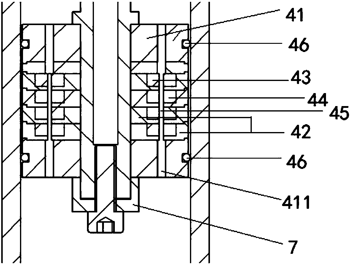
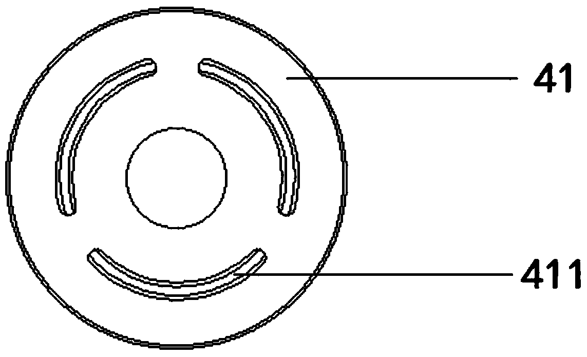
The invention discloses a staggered variable electrode giant electrorheological fluid damper which comprises a piston rod, a piston, a movable piston and a piston barrel. The piston sleeves to the lower end of the piston rod and can slide relative to the piston barrel; the upper end of the piston rod penetrates through an upper cover of the piston barrel; a movable seal structure is arranged between the piston rod and the upper cover; the movable piston is slidably connected with the piston barrel in a sealing way; and the movable piston is arranged between the piston and the piston barrel. The piston and the movable piston sequentially divide the inner part of the piston barrel into three chambers; giant electrorheological fluids are fully filled in the upper chamber and the lower chamber; and a gas chamber communicates with an outside atmosphere. Multiple annular electrodes are arranged in the piston, gaps are formed in the piston and pass through clearances between the annular electrodes, the annular electrodes are electrically connected with a controller, the controller can change the polarities of the annular electrodes, and the gaps communicate with the upper chamber and thelower chamber. According to the staggered variable electrode giant electrorheological fluid damper provided by the invention, through the staggered distribution of electrode polarities, a high dampingeffect can be favorably produced under the same voltage magnitude.

Description

technical field [0001] The present invention relates to the technical field of dampers, in particular to a staggered variable electrode giant electrorheological fluid damper. Background technique [0002] Electrophoretics are suspended liquids formed by dispersing small particles of high dielectric constant in a solvent of low dielectric constant. Under the action of an external electric field, the suspended liquid can polarize and interact with solid particles in milliseconds, forming a chain or columnar structure parallel to the electric field, so that the liquid behaves as a solid-like constitutive with a certain yield stress. The state increases the apparent viscosity by several orders of magnitude. This effect of changing the state of the fluid is called the electrorheological effect. [0003] Electrorheological damper is a widely used energy dissipation and vibration reduction control device, which can be used in machinery, construction and other fields. Its control ...

Claims


Application Information

Patent Timeline
IPC IPC(8): F16F9/53F16F9/32F16F9/06F16F9/34
CPCF16F9/067F16F9/068F16F9/3214F16F9/346F16F9/532
Inventor 蒲华燕孔桢孙翊汪小帆彭艳罗均杨毅谢少荣刘娜
Owner SHANGHAI UNIV
Learn More